FG8101G01
Technical Documentation
Page 20 of 49
Version: 01.02; Date: 18.11.2022
9
Extension boards
9.1
Mounting of extension boards
To mount an extension board, the blind cover of the corresponding position must be
removed first. To do this, the two captive screws of the blind cover must be removed
from the FG8101G01.
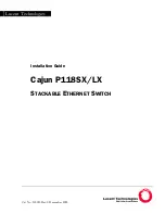
Figure 4
Figure 4 shows a FG8101G01 with the blind covers of POS1 and POS2 removed.
Then the extension board must be inserted into the desired position.
For POS2 to POS4 and POS6 to POS8, the circuit board of the extension board must be
inserted between the guides of the corresponding position (see Figure 5)
Figure 5