Honeywell TRADELINE VR8345M Скачать руководство пользователя страница 13

13

68-0160

4. If the desired outlet gas pressure or gas flow rate

cannot be achieved by adjusting the gas control, check the
gas control inlet pressure by using a manometer at the inlet
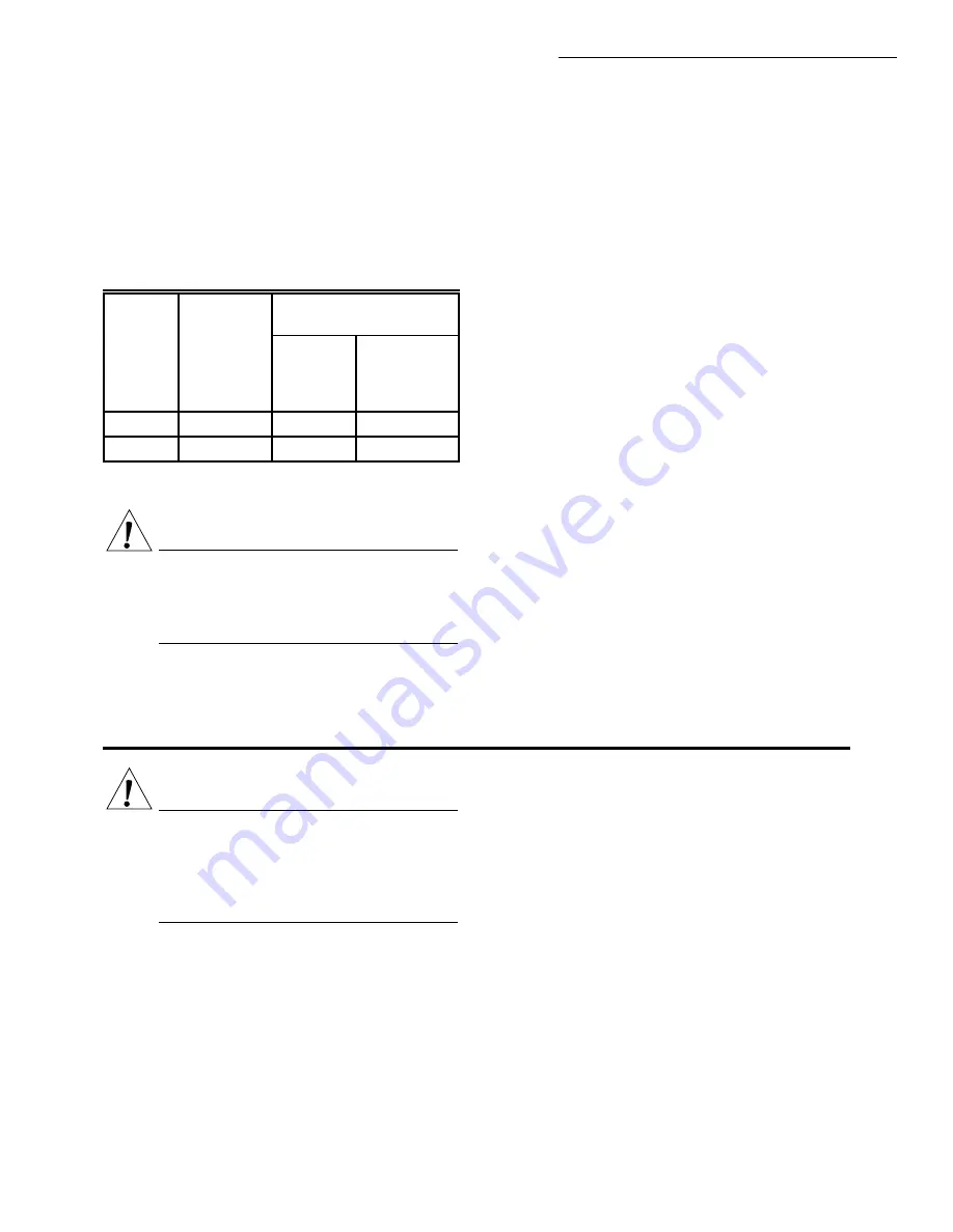
pressure tap. If the inlet pressure is in the normal range (refer
to Table 5), replace the gas control. Otherwise, take the
necessary steps to provide proper gas pressure to the gas
control.

TABLE 5—PRESSURE REGULATOR

SPECIFICATION PRESSURES FOR STANDARD-

OPENING NATURAL GAS.

NOTE: Read steps 1 through 7 below before starting and

compare to the safety shutdown or safety lockout tests
recommended for the intermittent pilot (IP), hot surface
(HSI) or direct spark (DSI) module. When  different, use
the procedure recommended for the module.

1. Turn off gas supply.
2. Set the thermostat or controller above room tempera-

ture to call for heat.

3. • Intermittent Pilot Ignition—Watch for an ignition

spark at pilot burner either immediately or follow-
ing prepurge. See ignition module specifications.

• Hot Surface or Direct Spark Ignition—Watch for

an ignition spark or glow at hot surface igniter
either immediately or following prepurge. See ig-
nition module specifications.

4. If module has timed ignition, time the length of the

igniter operation. See ignition module specifications.

5. • Intermittent Pilot Ignition—After the module locks

out, turn on gas supply and make sure there is no
gas flow to the pilot or main burner.

NOTE: With modules that continue spark until pilot lights or

system is shut down manually, pilot should light when
gas supply is turned on.

• Hot Surface or Direct Spark Ignition—After the

module locks out, turn on gas supply and assure
there is no gas flow to main burner.

6. Set the thermostat below room temperature and wait at

least 45 seconds to reset system.

7. Operate system through one complete cycle to make

sure all controls operate properly.

Maintenance

The maintenance program should include regular check-

out of the gas control; see Startup and Checkout section. To
check out the control system, see the appliance manufac-
turer literature. Maintenance frequency must be determined
individually for each application. Some considerations are:

• Cycling frequency. For appliances that may cycle

100,000 times annually, check monthly.

• Intermittent use. For appliances that are used season-

ally, check before shutdown and again before the next
use.

• Consequence of unexpected shutdown. Where the cost

of an unexpected shutdown would be high, check the
system more often.

• Dusty, wet, or corrosive environment. Because these

environments can cause the gas control to deteriorate
more rapidly, check the system more often.

NOTE: If the gas control will be exposed to high ammonia

conditions; e.g., those used in greenhouses or animal
barns,  contact your Honeywell sales representative to
request a gas control with corrosion resistant construction.

Outlet Pressure  

(Full Rate)

Unit  

of

Measure

Nominal

Inlet

Pressure

Range

Nominal

Factory

Outlet

Setting

Adjustment

Setting

Range

in. wc

5.0 - 7.0

3.5

3.0 - 5.0

kPa

1.2 - 1.7

0.9

0.7 - 1.2

CHECK SAFETY SHUTDOWN PERFORMANCE

WARNING

FIRE OR EXPLOSION HAZARD
CAN CAUSE PROPERTY DAMAGE,
SEVERE INJURY, OR DEATH

Perform the safety shutdown test any time work is
done on a gas system.

WARNING

FIRE OR EXPLOSION HAZARD
CAN CAUSE PROPERTY DAMAGE,
SEVERE INJURY, OR DEATH

Improper cleaning or reassembly can cause gas
leakage. When cleaning, be sure that the control is
reassembled properly and perform gas leak test.

Regular preventive maintenance is important in applica-

tions that place a heavy load on system controls such as
commercial cooking, agricultural and industrial operations
because:

• In many such applications, particularly commercial

cooking, the equipment operates 100,000 to 200,000
cycles per year. Such heavy cycling can wear out the
gas control in one to two years.

• Exposure to water, dirt, chemicals and heat can dam-

age the gas control and shut down the control system.

VR8345M

STARTUP AND CHECKOUT  •  MAINTENANCE

Содержание TRADELINE VR8345M

Страница 1: ...Works with virtually all residential equipment and all but the largest commercial equipment with a regulation capacity range of 30 000 to 415 000 Btuh natural gas 48 600 to 672 300 LP gas All adjustments and wiring connections accessible from top of control Straight through body pattern 1 8 in NPT inlet and outlet taps on top of gas control aid adjustment of gas pressure in problem installations 3...

Страница 2: ...conditions and some minor differences in performance can be expected if those conditions are changed MODEL VR8345M Universal Combination Gas Control AMBIENT TEMPERATURE RANGE 40 to 175 F 40 to 79 C BODY PATTERN Straight through REGULATOR TYPE Standard opening INLET X OUTLET SIZE 3 4 x 3 4 inch IGNITION ADAPTER Configures VR8345M to operate with direct spark or hot surface ignition ELECTRICAL RATIN...

Страница 3: ...ed service technician to re place the gas control Force or attempted repair can result in fire or explosion TABLE 3 VR8345 REPLACES THESE GAS CONTROLS Continued Replacement Gas Controls Universal Old Model No Manufacturer VR8200 VR8300 VR800 Replacement 36E36 304 DSI HSI WHITE RODGERS VR8205A2024 VR8305M3506 VR8450A4113 VR8345M4302a 36E36 304 IP WHITE RODGERS VR8204A2076 VR8304M3509 VR8440A3025 VR...

Страница 4: ...2024 VR8305M3506b VR8450A4113b VR8345M4302a b V8185A1001 HONEYWELL VR8205A2024 VR8305M3506 VR8450A4113 VR8345M4302a V8185A1019 HONEYWELL VR8205A2024 VR8305M3506 VR8450A4113 VR8345M4302a V8185A1035 HONEYWELL VR8205A2024 VR8305M3506 VR8450A4113 VR8345M4302a V8185B1009 HONEYWELL VR8205A2024 VR8305M3506 VR8450A4113 VR8345M4302a V8185B1017 HONEYWELL VR8205A2024 VR8305M3506 VR8450A4113 VR8345M4302a V824...

Страница 5: ...302e VR8440A2134 HONEYWELL VR8204A2076c VR8304M3509 VR8440A3025c VR8345M4302c VR8440A2142 HONEYWELL VR8204A2076 VR8304M3509 VR8440A3025 VR8345M4302 VR8440M1000 HONEYWELL VR8204A2076 VR8304M3509 VR8440A3025 VR8345M4302 VR8440M2008 HONEYWELL VR8204A2076 VR8304M3509 VR8440A3025 VR8345M4302 VR8440M2016 HONEYWELL VR8204A2076c VR8304M3509 VR8440A3025c VR8345M4302c VR8440M2024 HONEYWELL VR8204A2076 VR830...

Страница 6: ...with 1 8 in compression fitting part no 3934014 1 f Use with 3 4 in angle flange part no 393690 15 g Requires 1 2 in straight flange part no 393690 16 or an angle flange part no 393690 13 CAUTION Never apply a jumper across or short the valve coil terminals This can burn out the heat anticipator in the thermostat or damage the electronic intermit tent pilot IP module IMPORTANT These gas controls a...

Страница 7: ...tional Fuel Gas Code ANSI Z223 1 NFPA No 54 whichever applies Tubing installation must comply with approved standards and practices 1 Use new properly reamed pipe free from chips If tubing is used make sure the ends are square deburred and clean Make sure all tubing bends are smooth and without deformation 2 Run pipe or tubing to the gas control If tubing is used obtain a tube to pipe coupling to ...

Страница 8: ...ing to pilot burner manufacturer instructions Fig 6 Always use new compression fitting OUTLET PRESSURE TAP INLET OUTLET WIRING TERMINALS 2 INLET PRESSURE TAP PRESSURE REGULATOR ADJUSTMENT UNDER CAP SCREW CONVENIENCE TERMINALS 2 OPTIONAL PILOT OUTLET PILOT ADJUSTMENT UNDER CAP SCREW GAS CONTROL KNOB M8436 MUST USE WIRE ADAPTER NOT SHOWN ON HSI OR DSI SYSTEM MUST USE PILOT PLUG NOT SHOWN ON HSI OR D...

Страница 9: ...be in the valve pilot opening M8440 PV M V PV M V OFF ON PILOT GAS SEAL PLUG WIRE ADAPTER All wiring including insulated quick connect terminals mustcomplywithapplicableelectricalcodesandordinances 1 Check the power supply rating on the gas control and make sure it matches the available supply Install thermostat and other controls as required 2 When the gas control is installed on a hot surface or...

Страница 10: ...OR Q354 FLAME SENSOR LIMIT CONTROLLER THERMOSTAT OR CONTROLLER POWER SUPPLY PROVIDE DISCONNECT MEANS AND OVERLOAD PROTECTION AS REQUIRED MAKE SURE L1 AND L2 ARE NOT REVERSED THIS WOULD PREVENT FLAME DETECTION ALTERNATE LIMIT CONTROLLER LOCATION SENSE TERMINAL AND Q354 FLAME SENSOR ON D MODELS ONLY BURNER GROUND M8563 QUICK CONNECTS AUTO IGNITION SYSTEMS ANSI Z21 20 STATUS LED 1 Flash Ignition Lock...

Страница 11: ...JURY OR DEATH Check for gas leaks with a rich soap and water solution anytime work is done on a gas control GAS LEAK TEST 1 Paint all pipe connections upstream of the gas control with a rich soap and water solution Bubbles indicate a gas leak 2 If a gas leak is detected tighten the pipe connection WARNING FIRE OR EXPLOSION HAZARD CAN CAUSE PROPERTY DAMAGE SEVERE INJURY OR DEATH 1 Donotforcethegasc...

Страница 12: ...CKING GAS INPUT BY CLOCKING THE GAS METER Make sure that the only gas flow through the meter is that of the appliance being checked Makecertainthatotherappliancesareturned off with pilot burners extinguished or de duct that gas consumption from the meter reading Convert the flow rate to Btuh as described in Gas Controls Handbook form 70 2602 and compare to the Btuh input rating on the appliance na...

Страница 13: ...programshouldincluderegularcheck out of the gas control see Startup and Checkout section To check out the control system see the appliance manufac turerliterature Maintenancefrequencymustbedetermined individually for each application Some considerations are Cycling frequency For appliances that may cycle 100 000 times annually check monthly Intermittent use For appliances that are used season ally...

Страница 14: ...lls for heat the DI module generates a spark at the main burner and the first automatic valve and second automatic valve operators are energized Fig 14 The first automatic valve opens and the second automatic valve operator valve disk is lifted off its seat This diverts gas flow from the second automatic valve diaphragm and causes a reduction of pressure on the underside of this diaphragm The redu...

Страница 15: ...e regulator diaphragm moves slightly higher allowing less gas flow to the gas control outlet This increases gas pressure under the automatic valve diaphragm and repositions the valve disk closer to the seat Thus flow of gas through the second automatic valve is reduced and outlet pressure falls to the desired level If outlet pressure begins to fall the pressure regulator diaphragmmovesslightlylowe...

Страница 16: ...N TRACING GAS FLOW SLOW OPENING GAS CONTROL HAS A GAS FLOW RESTRICTOR IN THIS PASSAGE M9126 1 1 PILOT GAS OUTLET Fig 15 Direct Ignition Intermittent Pilot Applications Position of gas control components during thermostat off cycle FIRST AUTOMATIC VALVE SOLENOID CONTROL KNOB GAS CONTROL INLET SECOND AUTOMATIC VALVE OPERATOR SECOND AUTOMATIC OPERATOR SOLENOID SECOND AUTOMATIC OPERATOR VALVE DISC SER...

Страница 17: ...m temperature while you are away COMPLETE SHUTDOWN Push in the gas control knob slightly and turn clockwise to OFF Do not force Appliance will completely shut off Follow the In structions to the Homeowner above to resume normal operation VR8345M SERVICE WARNING FIRE OR EXPLOSION HAZARD CAN CAUSE PROPERTY DAMAGE SEVERE INJURY OR DEATH Do not disassemble the gas control it contains no replaceable co...

Страница 18: ...68 0160 18 ...

Страница 19: ...19 68 0160 ...

Страница 20: ...ou Control Your World Honeywell Inc Honeywell Limited Honeywell Limitée 1985 Douglas Drive North 740 Ellesmere Road Golden Valley MN 55422 Scarborough Ontario M1P 2V9 Printed in U S A QUALITY IS KEY Printed on recycled paper containing at least 10 post consumer paper fibers ...

Отзывы: