TP790 AND TP9600 SERIES PNEUMATIC THERMOSTATS
11
77-9382—1
The TP972A and TP9620A have one setpoint adjustment
knob that controls both heating and cooling bimetals. Each
bimetal has an independent throttling range adjustment
(Fig. 16). The cooling bimetal of the TP972A and TP9620A
controls when the two-pressure air supply is at the lower of
the two pressures; the heating bimetal of the TP972A and
TP9620A controls when air supply pressure increases to the
higher of the two pressures. Typical values for the two-
pressure supply systems are 13/18 psi (90/124 kPa),
16/21 psi (110/145 kPa), and 20/25 psi (138/172 kPa).
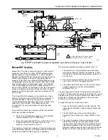
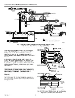
Figures 17 and 18 are schematic representations of the
TP972A and TP9620A airflow paths for heating and cooling
control. Operation is the same as that for the TP971 and
TP9610 except for the logic modules, the manual override,
and the independent setpoint adjustment. Cooling control
requires a lower pressure in the main air supply. Figure 17
shows the workings and traces the air path within the
TP972A and TP9620A when it is controlling with the cooling
bimetal.
NOTE:
The TP972A2036, A2168, and A2176 and TP9620A
limited-control-range Thermostats have separate,
concealed setpoints for heating and cooling and
limit the heating control point to a maximum of
75
°
F (24
°
C).
Fig. 17. TP972A and TP9620A Operation on Cooling Cycle—Main Air Pressure 13 psi (90 kPa).
Fig. 18. TP972A and TP9620A Operation on Heating Cycle—Main Air Pressure at 18 psi (124 kPa).
B
BLEED 1
F
FILTER
RESTRICTOR
R
VALVE
UNIT
S
S
LOGIC
MODULE A
LOGIC
MODULE B
BRANCH LINE
MAIN LINE
PILOT
CHAMBER
SPRING
DIAPHRAGM
PORT B2
PORT B1
13 PSI (90 kPa)
SUMMER
18 PSI (124 kPa)
WINTER
C6062-1
SPRING
B
BLEED 1
F
FILTER
RESTRICTOR
R
VALVE
UNIT
S
S
LOGIC
MODULE A
LOGIC
MODULE B
BRANCH LINE
MAIN LINE
PILOT
CHAMBER
SPRING
DIAPHRAGM
PORT B2
PORT B1
13 PSI (90 kPa)
SUMMER
18 PSI (124 kPa)
WINTER
C6063-1
SPRING

