background image

TP790 AND TP9600 SERIES PNEUMATIC THERMOSTATS

9

77-9382—1

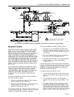
Fig. 14. TP971 and TP9610 Operation on Nighttime Cycle—Main Air Pressure 18 psi (124 kPa).

BLEED 1

F

FILTER

RESTRICTOR

R

VALVE

UNIT

SECONDARY

BRANCH

S

1

1

S

S

B

DAY/AUTO LEVER

MANUAL DAY

LOGIC

MODULE C

LOGIC

MODULE D

SPRING

LOGIC MODULE  A

DOTTED LINES INDICATE THE SECONDARY
BRANCH LINE INTEGRAL TO THE TP971C 

BRANCH LINE

MAIN LINE

PILOT

CHAMBER

SPRING

BLEED 2

DIAPHRAGM

 PORT B2

 PORT B1

13 PSI (90 kPa)

DAY

18 PSI (124 kPa)

NIGHT

LOGIC

MODULE B

C6059-1

B

Manual DAY Override

Manual DAY Override is shown in Figure 15. With main air
pressure at the 18 psi (124 kPa) (NIGHT) setting, airflow
applies pressure to Logic Modules A, C, and D. However,
because the DAY/AUTO lever has been manually positioned
to DAY, Logic Module D is shut off, stopping airflow. Air
pressure is bled from Logic Module B through Bleed 2, and
the diaphragm moves up to open Port B1 and close Port B2.
This condition allows an airflow path to the 13 psi (90 kPa)
(DAY) nozzle-flapper and closes the airflow path to the 18
psi (124 kPa) (NIGHT) nozzle-flapper. Thus, the Thermostat
works on a daytime cycle even though the main air supply
pressure is at its normal night cycle main air pressure of 18
psi (124 kPa).

The 18 psi (124 kPa) pressure on the diaphragm of Logic
Module C holds the manual DAY/AUTO lever in position. If
the occupant fails to return the override lever, the lever
returns automatically when the system main air pressure is
reduced to 13 psi (90 kPa). This change returns the
Thermostat to its normal operation and automatic logic
switchover.

The secondary branch line operates with the manual DAY/
AUTO lever position as follows:

1. System in normal daytime operation, 13 psi (90 kPa)

main air pressure (Fig. 13 dotted lines).

2. Move the manual DAY/AUTO lever to the DAY position.

It snaps back to AUTO because there is no air
pressure on logic switch C (Fig. 13).

The secondary branch line is always at the main air pressure
when the system operates in a daytime mode; the P/E switch
contacts are closed and the supply fan is operating.

During normal nighttime operation conditions (Fig. 14):

1. The system is in normal nighttime operation mode;

main and secondary branchline air pressure is at 18
psi (124 kPa). The secondary branch line is also at 18
psi (124 kPa).

2. Since the P/E switch contacts open at any pressure

over 15 psi (103 kPa), the supply fan is off.

3. The manual DAY/AUTO lever is in the AUTO position

because operation is under normal nighttime
conditions (Fig. 14).

The secondary branch line is at the night main air pressure
of 18 psi (124 kPa) when the system is operating in a normal
nighttime mode. The P/E switch contacts are open and the
supply fan is off because the pressure in the secondary
branch is over 15 psi (103 kPa).

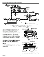
For night occupancy and daytime control:

1. Push the DAY/AUTO switch to the DAY position. This

opens the nozzle-bleed on the secondary branch line
(Fig. 15).

2. The DAY/AUTO lever stays in the DAY position

because of the air pressure on Logic Module C (Fig.
15).

3. The main air pressure in the secondary branch line

bleeds down through the secondary branch nozzle.
The secondary branchline restrictor maintains normal
night system pressure in the rest of the Thermostat.
However, airflow is now diverted to operate the nozzle-
flapper on the DAY mode sensing element (Fig. 15).

Содержание TP9600 Series

Страница 1: ...ts 4 General 4 Operation 5 Direct Action 5 Reverse Action 5 TP970A D and TP9600A B High Capacity Single Temperature Thermostats 6 General 6 Operation 6 Direct Action 6 Reverse Action 7 TP971A C and TP9610A B High Capacity Dual Temperature Thermostats 7 TP971B and TP9610B 7 TP971C 7 TP971A and TP9610A 7 Daytime Operation 8 Nighttime Operation 8 Manual DAY Override 9 TP972A and TP9620A High Capacity...

Страница 2: ... a fixed branchline pressure BLP for each temperature within the temperature and throttling range settings The forces within the nozzle flapper bimetal assembly always seek a balanced condition giving the same BLP for the same temperature regardless of fluctuations in main air or the relative positions of the nozzle flapper and bimetal Flapper Nozzle Operation Flapper nozzle operation is generally...

Страница 3: ...METAL FILTER RESTRICTOR BRANCH LINE THROTTLING RANGE ADJUSTMENT CALIBRATION SCREW SETPOINT CAM SETPOINT KNOB NOZZLE BRANCHLINE PRESSURE TAP BRANCHLINE CHAMBER BLEED PILOT PILOT CHAMBER EXHAUST VALVE MAIN LINE TP970 TP9600 TP971 TP9610 TP972 and TP9620 Thermostats are designed around a valve unit for flow amplification rather than conventional pressure amplification Branchline chamber and pilot cha...

Страница 4: ... operation is very important to understanding TP970 TP9600 TP971 TP9610 TP972 and TP9620 operation As can be seen from Figures 3 4 and 5 pilot pressure changes affect BLP changes in the same ratio There is no pressure gain to amplify errors as with other pneumatic Thermostats Still the main air supply being switched through the valve unit provides fast high capacity increase and decrease of BLP TP...

Страница 5: ... the bimetal are again in equilibrium with the opposing force 8 psi 55 kPa times the area of the nozzle at the flapper A reduction in setpoint causes the reverse to happen The calibration screw allows for matching the bimetal start position with the indicated setting on the setpoint cam to achieve an 8 psi 55 kPa BLP at the indicated setpoint The TR adjustment Fig 9 provides a means for changing t...

Страница 6: ...reater temperature change at the bimetal to throttle the flapper over the nozzle The result is a wider TR or very low sensitivity for instance a 1 F 0 56 C change in temperature results in only a 1 psi 7 kPa BLP change TP970A D AND TP9600A B HIGH CAPACITY SINGLE TEMPERATURE THERMOSTATS General The TP970 and TP9600A B Thermostats Fig 10 are the basic TP973 with a valve unit added for greater capaci...

Страница 7: ... TP9610A On the TP971A and TP9610A direct acting Thermostats Fig 12 the daytime bimetal controls the system when the main air pressure is 13 psi 90 kPa The nighttime element controls the system when the main air pressure reaches 18 psi 124 kPa Models are available with switchover pressures of 16 to 21 psi 110 to 145 kPa and 20 to 25 psi 138 to 172 kPa Fig 12 TP971 and TP9610 Day Night Thermostat T...

Страница 8: ...and TP9610 Operation on Day Cycle Main Air Pressure 13 psi 90 kPa Nighttime Operation In Figure 14 the main air pressure is at 18 psi 124 kPa for nighttime operation The airflow shown by arrows is the same as the daytime cycle up to Logic Module A and Logic Module B The main air pressure 18 psi 124 kPa is now enough to overcome the spring loaded diaphragm in Logic Module A Because the manual overr...

Страница 9: ...ic switchover The secondary branch line operates with the manual DAY AUTO lever position as follows 1 System in normal daytime operation 13 psi 90 kPa main air pressure Fig 13 dotted lines 2 Move the manual DAY AUTO lever to the DAY position It snaps back to AUTO because there is no air pressure on logic switch C Fig 13 The secondary branch line is always at the main air pressure when the system o...

Страница 10: ... the system to normal operation by manually switching the DAY AUTO lever to AUTO In the preceding situation the P E switch contacts are closed This is because the secondary BLP is under 15 psi 103 kPa the DAY AUTO lever is held in the DAY position by pressure on Logic Module C and the Thermostat uses its daytime bimetal because the airflow through Logic Module D is closed off TP972A AND TP9620A HI...

Страница 11: ...rride and the independent setpoint adjustment Cooling control requires a lower pressure in the main air supply Figure 17 shows the workings and traces the air path within the TP972A and TP9620A when it is controlling with the cooling bimetal NOTE The TP972A2036 A2168 and A2176 and TP9620A limited control range Thermostats have separate concealed setpoints for heating and cooling and limit the heat...

Страница 12: ... the Module The air pressure is applied to the diaphragm of Logic Module B closing off Port B1 and opening Port B2 Now the air is directed to the flapper nozzle of the heating bimetal and the Thermostat controls in the heating mode TP974A ROOM TEMPERATURE SENSOR General The TP974A Fig 19 20 is a bimetal element proportioning temperature sensor for either two or one pipe applications The sensor bim...

Отзывы: