2
I56-3433-004
04-12
nals automatically reset upon removing the cause of trouble. Red and yellow
LEDs can be remotely connected to the remote Alarm and Trouble outputs.
These outputs mimic the functions of the detector’s red and yellow LEDs.
In addition to these indicators, there is a dual digital display that reads 00 to
99. This display is used to indicate the signal strength of the beam in align-
ment mode and to indicate the sensitivity setting of the detector in percent
obscuration when setting the sensitivity of the detector. No additional equip-
ment is needed for alignment of the beam.
SPECIAL APPLICATIONS
Due to the inherent capabilities of projected type beam detectors they are
often installed in locations where spot-type detection is impractical. Projected
type beam smoke detectors are ideally suited for environmental conditions
that might include high ceilings, dusty and dirty environments, or environ-
ments that experience temperature extremes. Often these conditions present
special problems for the installation of spot-type detectors and even greater
problems for their proper maintenance. Due to the inherent flexibility of
mounting locations and large coverage area of projected type beam detectors
often the conditions above can be addressed or minimized.
Some examples of applications for beam detectors might include freezers, air-
craft hangars, cold storage warehouses, shipping warehouses, enclosed park-
ing facilities, sporting arenas and stadiums, concert halls, barns, or stables.
Some of these environments might be considered too hostile for spot-type
smoke detectors. If the environment is considered to be hostile then the colder
alarm threshold settings should be used.
Before installing the transmitter/receiver unit or reflector in these types of
applications special consideration should be given to insure proper operation
of the beam detector. The beam detector should not be installed in environ-
ments where heavy condensation or icing is likely. Condensation or icing of
the reflector surface or the outer surface of the transmitter/receiver unit will
obscure the light beam resulting in a false alarm. If elevated humidity levels
and rapidly changing temperatures can be expected then condensation will
likely form and the application should not be considered acceptable for the
beam detector.
APPROVED ACCESSORIES
The following accessories can be purchased separately for use with this beam
detector.
BEAMLRK
The BEAMLRK allows reflected beam detectors to be installed at separations
between 230 and 328 feet (70 to 100 meters). At these distances, four 8˝ ×
8˝ reflectors must be used to provide enough reflected infrared light. This
kit includes 3 additional reflectors with new test scale legends. The reflector
included with the transmitter/receiver unit is the fourth reflector to be used.
This kit is not compatible with the multi-mount kit (BEAMMMK).
BEAMMMK
The BEAMMMK allows reflected beam detectors and reflectors to be mounted
to either a vertical wall or the ceiling. The kit allows for additional alignment
range in cases where the detector and reflector cannot be mounted within
10° of each other. The kit includes the hardware necessary to mount either
a single transmitter/receiver unit or a single reflector. (To mount the trans-
mitter/receiver the surface mount kit, BEAMSMK, must also be used). If the
transmitter/receiver and the reflector require additional alignment range two
kits are required. The kit is not compatible with the long-range reflector kit
(BEAMLRK).
BEAMSMK
The BEAMSMK allows reflected beam detectors to be mounted when surface
wiring is used. This kit must be used when mounting the transmitter/receiver
unit with the multi-mount kit (BEAMMMK).
6500-MMK
The 6500-MMK provides a heavy-duty multi-mount bracket for installations
prone to building movement or vibration. It offers similar tilt and swivel flex-
ibility found on the BEAMMMK. (To mount the transmitter/receiver to the
6500-MMK, the surface mount kit, 6500-SMK, must be used).
6500-SMK
The 6500-SMK allows the transmitter/receiver to be mounted to the 6500-
MMK heavy duty multi-mount kit.
BEAMHK
The BEAMHK allows the transmitter/receiver unit to operate in environments
prone to the formation of condensation. Condensation forming on the beam
detector unit may result in trouble or false alarm conditions. BEAMHK will
lessen the likelihood of condensation by maintaining the unit at a temperature
that is slightly higher than the surrounding air. Please refer to the BEAMHK
installation manual for operation instructions.
BEAMHKR
The BEAMHKR allows the reflector to operate in environments prone to the
formation of condensation. Condensation forming on the reflector may re-
sult in trouble or false alarm conditions. BEAMHKR will lessen the likelihood
of condensation by maintaining the reflector at a temperature that is slightly
higher than surrounding air. The kit requires a 24V power supply. When used
with the long-range reflector kit (BEAMLRK), it is necessary to purchase and
install four BEAMHKR kits. Please refer to the BEAMHKR installation manual
for operation instructions.
RTS451/RTS451KEY/RTS151/RTS151KEY
The remote test accessory, RTS451/RTS451KEY or RTS151/RTS151KEY, allows
for the beam detector to be tested remotely. The test accessory provides test and
reset functions and green and red LED’s that mimic the LEDs on the detector.
PARTS LIST
Description
Quantity
Transmitter/Receiver Unit . . . . . . . . . . . . . . . . . . . . . . . . . . . . . . . . . . . . .1
Paintable Trim Ring . . . . . . . . . . . . . . . . . . . . . . . . . . . . . . . . . . . . . . . . .1
Reflector
. . . . . . . . . . . . . . . . . . . . . . . . . . . . . . . . . . . . . . . . . . . . . .1
Plug-in Terminal Blocks . . . . . . . . . . . . . . . . . . . . . . . . . . . . . . . . . . . . . .3
Isolator Shunts . . . . . . . . . . . . . . . . . . . . . . . . . . . . . . . . . . . . . . . . . . . .2
Instruction Manual . . . . . . . . . . . . . . . . . . . . . . . . . . . . . . . . . . . . . . . . .1
Orange Paper Sheet . . . . . . . . . . . . . . . . . . . . . . . . . . . . . . . . . . . . . . . . .1
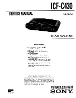
PARTS DIAGRAM (NOT TO SCALE)
TERMINAL BLOCK
ISOLATOR
SHUNT
PAINTABLE TRIM RING
C0306-00
DETECTOR PLACEMENT
This section of the manual discusses the placement of projected beam detec-
tors. Though this information is based upon industry expertise, it is intended
to be used only as a technical guide. Always comply with the requirements of
applicable codes and standards such as, NFPA 72, National Fire Alarm Code,
as well as directives of the Authority Having Jurisdiction (AHJ).
Projected beam detectors are usually located with their beams parallel to the
ceiling. However, they can be mounted vertically or at any angle to protect the
area involved. Since beam detectors sense the smoke buildup over a distance,
they are ideal for locations with high ceilings. They can also be mounted on a
wall or ceiling below the level of a spot type detector, reducing the effects of
air stratification. Some typical locations would include large areas with high
ceilings such as atriums, warehouses, and factories.
NOTE:
Projected beam smoke detectors should always be mounted to sta-
ble mounting surfaces. See the MOUNTING LOCATION section for details.
Some fire codes specify spacing on a given center-to-center distance between
detectors under ideal conditions. This spacing is based on rooms with smooth
ceilings and no physical obstructions between the contents being protected
and the detectors. Moreover, they are also based on a maximum ceiling height,
and on the assumption that the value and the combustible nature of the con-
tents of the room being protected do not warrant greater protection or closer
spacing.
Содержание SK-Beam
Страница 10: ...10 I56 3433 004 04 12 ...
Страница 11: ...11 I56 3433 004 04 12 APPENDIX II DETECTOR DRILLING TEMPLATE 4 345 6 190 157 mm 110 mm Scale 1 1 C0278 00 ...
Страница 12: ...12 I56 3433 004 04 12 ...
Страница 13: ...13 I56 3433 004 04 12 APPENDIX III REFLECTOR DRILLING TEMPLATE 5 512 140mm 8 465 215mm Scale 1 1 C0279 00 ...