EN2R-9031 0402R15-NE
40
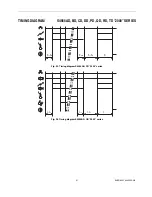
Fig. 48. Timing diagram S4565DF and TF with external main burner interrupt in fan assisted applications
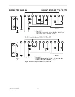
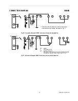
Fig. 49. Connection diagram S4565DF, TF with external main burner interrupt in atmospheric applications
P
T
s
PV
MV
T
c+
T
w
T
c+
T
w
T
FR
MBI
T
stab
L
N
Side connections**
LM
RS
Optional
*
22 K
CNY 17-3
12
11
10
9
8
7
6
5
4
3
2
1
*
See note 17.
** Alternative side connection for models with combined flame
detection/high voltage. See page 56. Fig. 71.


