background image

P7810A-D PRESSURETROL® CONTROLLER

65-0268—1

8

The High Limit Setpoint can be set above the internal stored 

Maximum Fixed Stop Limit Value but it will have no functional 

effect. For example the internal stored Maximum Fixed Stop 

Limit Value is 12 psi and the knob is set at 14 psi. Lockout will 

occur at 12 psi. the LED pattern will be green on and yellow 

blinking fast.

When pressure increases to the high limit setpoint, the (1K1, 

2K1) relay contacts open and the P7810C,D indicates a safety 

lockout by alternately flashing the yellow and green LEDs. 

The P7810C,D remains in this condition until the manual reset 

button (see Fig. 1) is pressed. The Alarm (3K1) relay contacts 

will close, providing a 120 Vac output on the Alarm terminal.

Reset Switch Functions

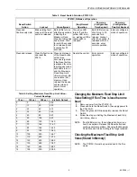
The Reset Switch has the functions listed in Tables 4 and 5.

Table 4. Reset Switch Function, P7810A,B.

P7810 Pressuretrol® Controller Setup

For P7810B,C and D Pressuretrol® Controllers with more 

than one function(control, modulate and high limit [P7810C 

and D]), adjust setpoints and differentials separately for each 

function.

CAUTION

Equipment Damage Hazard.

Improper setting of control setpoint and control 

range knob errors can damage the P7810.

Do not set control setpoint or control range knob 

arrows past the scale plate endpoints.

Adjust setpoints and differentials using the knobs on the front 

of the P7810 Pressuretrol® Controller.

Set the knobs to the desired points by aligning the center of 

the knob arrow with the desired mark on the scale plate. See 

Fig. 13.

Fig. 13. Setting control setpoint and control range knobs.

IMPORTANT

P7810C,D devices must set Maximum Fixed Stop 

Limit Value function first.

Setting Maximum Fixed Stop Limit Value 

(P7810C,D)

CAUTION

Equipment Damage Hazard.

Exceeding pressure vessel limits can damage 

equipment.

The 

Maximum Fixed Stop Limit

 pressure setting 

must not

 exceed the maximum working pressure 

rating of the pressure vessel. Adjust the 

Maximum 

Fixed Stop Limit

 setting to maximum working 

pressure rating that is stamped on the pressure vessel 

by the manufacturer. 

IMPORTANT

The Maximum Fixed Stop Limit Value must be 

programmed first for the P7810C or D to operate.

1.

Initial Startup—Maximum Fixed Stop Limit Value is 

unprogrammed.

a. Green LED (Control LED)—Blinking rapidly (1/2 

second on, 1/2 second off).

b. Yellow LED (Power LED)—On steady and bright. 

2.

Setting the Maximum Fixed Stop Limit Value.

a. Monitor the 4 to 20 mA output. Long filtering delays 

cause a lag between the 4 to 20 mA output and the 

limit setting, i.e., 20 to 25 seconds for a full scale 

change.

b. Turn the Limit Setpoint knob to the desired setting 

and confirm by comparing the current noted to the 

corresponding reading in Table 6. Ensure that the 

mA output is stable before using the value.

c. Press and hold the Reset Switch.

d. Release the Reset Switch when both LEDs turn on.

e. The Maximum Fixed Stop Limit Value is set and the 

device will recycle and attempt to enter Run mode.

f. After an accumulated run time (Call for Heat) of one 

hour, the Maximum Fixed Stop Limit Value setting 

will be permanently stored in the P7810C,D 

memory. Changing the Maximum Fixed Stop Limit 

Value setting after this time will then be ineffective.

Reset Switch Action

P7810A,B Modes of Operation

Lockout

(Run) Normal Operation

Press and Continuously Hold

Blink existing fault code until the reset 

switch is released.

The green LED turns off and the yellow 

LED turns on, waiting until the reset 

switch is released.

Press and Release

Clear the fault code and reset the P7810. Resets the control.

DIAL ARROW

SCALE 
PLATE

M4880A 

Содержание Pressuretrol P7810A

Страница 1: ...rode the pressure sensing element Models available with on off control function on off control and modulate high limit and modulate and on off control and safety high limit functions Models available in 15 150 and 300 psi 103 1034 and 2069 kPa maximum setpoints LED indicators show power call for heat function and lockout status Clear cover allows setpoint and differential to be read but not adjust...

Страница 2: ...ntact Ratings a P7810C D models only Sensor Material 304 stainless steel Pressure Connector P7810A B 1 4 in NPT P7810C D 1 2 in NPT Case Material Plastic Electrical Terminations Screw terminals Accuracy 4 0 percent full scale output operating range over operating temperature Environmental Ratings Operating Temperature Range 32 F to 140 F 0 C to 60 C Storage Temperature Range 20 F to 150 F 29 C to ...

Страница 3: ...fore removing old control 3 Follow all installation and checkout procedures for safe installation IMPORTANT Do not remove the overpressure inlet seal until ready to connect piping to prevent contamination of inlet Location Install the P7810 Pressuretrol Controller above the boiler water line when used with steam boilers Connect the siphon loop part number 14026 for P7810A B 209731A for P7810C D or...

Страница 4: ...with an approved weather tight enclosure CAUTION Equipment Damage Hazard Incorrect installation of the L404 Pressure Controller can damage the equipment and may require boiler replacement Install the L404C Pressuretrol as shown in Fig 2 and 3 to prevent equipment damage Fig 2 Connecting P7810A B Pressuretrol Controller to steam boiler Fig 3 Right and wrong mounting of steam trap siphon loop for th...

Страница 5: ...onnect may be involved All wiring must comply with applicable electrical codes ordinances and regulations Use NEC Class 1 line voltage wiring For normal installation use moisture resistant No 14 wire maximum size allowed suitable for at least 167 F 75 C or 194 F 90 C for Flame Safeguard Primary Controls Use shielded wire for 4 to 20 mA modulating output and terminate the shield to earth ground Do ...

Страница 6: ...1 2 12 13 15 14 R B W 4 TO 20mA ALARM FIELD WIRING 2K1 1K1 DEVICE WIRING OUTPUT 3K1 14 LOW FIRE 15 MODULATE 13 COMMON 8K1 8K2 9K2 9K1 AUTO MAN 66 5 OHM 237 OHM 12 HIGH FIRE 7800 SERIES PROGRAMMER W M20568C R B MODUTROL IV MOTOR CONTROLLER P7810 4 2O mA SERIES 90 1K OHM 7800 SERIES SHOWN REFER TO SPECIFICATIONS PACKED WITH THE PROGRAMMER FOR WIRING OF OTHER PRIMARY SAFETY CONTROLLERS 1 1 LOW FIRE 1...

Страница 7: ...ferential setting This cycle continues until power is removed opening the relay See Fig 11 Fig 11 P7810 on off control function versus pressure Modulate Control Function P7810B C Only When the pressure decreases to or below the modulation setpoint the current is 20 mA The current remains constant at all pressures below the modulation setpoint The modulation range is an additive value to the modula...

Страница 8: ...ed Stop Limit Value P7810C D CAUTION Equipment Damage Hazard Exceeding pressure vessel limits can damage equipment The Maximum Fixed Stop Limit pressure setting must not exceed the maximum working pressure rating of the pressure vessel Adjust the Maximum Fixed Stop Limit setting to maximum working pressure rating that is stamped on the pressure vessel by the manufacturer IMPORTANT The Maximum Fixe...

Страница 9: ...g fault code until the reset switch is released Both LEDs turn on after three seconds indicating the Maximum Fixed Stop Limit Value has been stored Wait for up to 30 seconds for a release Enter lockout after 30 seconds The green LED turns off and the yellow LED turns on waiting until the reset switch is released Both LEDs turn on Wait for up to 30 seconds for a release Lockout after 30 seconds If ...

Страница 10: ...te Control P7810B C Only The P7810B C adds 4 to 20 mA modulation output and uses two additional potentiometers The pressure sensor output is fed to an error and gain amplifier to perform the modulation determined by the control potentiometer settings The potentiometer knobs mounted on the P7810B C face adjust the current output for a given set of pressures The modulation range is an additive value...

Страница 11: ...form these tests the boiler pressure should be near the middle of the P7810 pressure range 2 Turn the P7810 limit setpoint knob fully clockwise to make sure this limit does not interfere during steps 4 and 5 This setting must return to the proper operating position when returning the system to normal operation 3 Check the control setpoint and control differential 4 Set the control differential kno...

Страница 12: ...obs to the required operating position 2 Press the reset button to clear the safety lockout condition 3 Start the system and observe the operation through at least one complete cycle to make sure the P7810 functions properly as described in the Operation section TROUBLESHOOTING WARNING Electrical Shock Hazard Can cause severe injury death or property damage Line voltage is present at the P7810 and...

Отзывы: