Honeywell ML7284 Скачать руководство пользователя страница 7

ML7284 NON-SPRING RETURN DIRECT COUPLED DAMPER ACTUATOR

63-2504—2

7

L1 
(HOT)

L2

1

1

BROWN

WHITE

BROWN

WHITE

RED

BLACK

ML7284

ML7284

RED

BLACK

M7617A

POWER SUPPLY.  PROVIDE DISCONNECT MEANS 
AND OVERLOAD PROTECTION AS REQUIRED.

PROPORTIONING
CONTROLLER

FEEDBACK

INPUT

FEEDBACK

INPUT

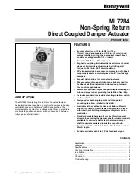
Fig. 8. Common transformer with one

controller output and two actuators.

Wiring

CAUTION

Disconnect power supply before wiring to prevent
electrical shock or equipment damage.

All wiring must comply with local electrical codes, ordinances
and regulations. The ML7284 is designed for use with a Class 2
power supply. Voltage and frequency of the transformer used
must correspond with the characteristics of the motor and those
of the power supply.  Standard mechanical connection is shown
in Fig. 4. See Fig. 5 for a typical wiring connection.

The ML7284 has a plastic housing with two tapped holes for
1/2 in. conduit fittings.

ML7284 Models with Factory-mounted Auxiliary
Switches (See Fig. 6)

ML7284C,F models have two nonadjustable low voltage rated
spdt auxiliary switches that are factory set to make common
to normally open at 12

°

 and 82

°

 rotation from the closed

(counter-clockwise) stop. See Fig. 6.

OPERATION

The ML7284 Non-Spring Return Direct Coupled Damper
Actuator is designed to be used in ventilating and air condi-
tioning installations to operate dampers, ventilation flaps and
louvers requiring up to 150 lb-in. torque.

The ML7284 Non-Spring Return Direct Coupled Damper
Actuator is operated by a proportional controller. When using
a proportional controller, the actuator is driven toward its
fully open position when the input signal increases and
toward the fully closed position when the input signal
decreases. The actuator stops when the input signal
reaches the desired proportional control point.

Use the rotation reversal slide switch to reverse the actuator
rotation. The switch is located on the side of the actuator
housing. See Fig. 9. To change the rotation to counter-
clockwise          , change the slide switch. Example: In direct
position 2 volts is closed and 10 volts is open. In reverse
position 2 volts is open and 10 volts is closed.

M7830

30

30

0

60

60

90

12

12

ROTATION
REVERSAL
SWITCH

REVERSE

DIRECT

Fig. 9. Location of ML7284 rotation

reversal slide switch.

Содержание ML7284

Страница 1: ... 90 low leakage dampers Manual clutch allows for manual adjustment 92 second synchronous timing can eliminate need for feedback position indication in closed loop tempera ture control applications Removable splined output hub permits premounting of hub on damper shaft providing installation flexibility Includes standard reverse direct acting rotation switch on the outside cover Designed for both s...

Страница 2: ...torage Temperature 30 F to 150 F 40 C to 65 C Humidity 5 to 95 percent relative humidity noncondensing Mounting Mounts directly on 3 8 in to 3 4 in 12 to 19 mm round or square damper shaft Minimum shaft length required 2 5 in 64 mm when the shaft attachment is made on the side of the actuator opposite the duct 0 65 in 16 mm when the hub is mounted on the shaft before the actuator is installed Most...

Страница 3: ...tor and mounting bracket in in mm 9 32 7 3 PLACES 1 17 32 39 3 3 32 79 4 102 7 16 11 1 1 4 32 7 11 16 196 8 7 16 215 36 914 1 2 12 5 8 17 13 32 10 1 2 13 3 4 19 7 8 22 1 25 3 5 32 80 1 2 13 1 2 13 1 11 16 43 2 1 2 63 3 5 16 84 4 1 2 114 5 127 6 152 1 4 6 1 1 REMOVABLE RETAINING RING FOR REMOVAL OF HUB SLEEVE M7618B 1 4 6 1 8 3 2 51 15 16 24 1 29 32 48 ...

Страница 4: ...ion The ML7284 Non Spring Return Direct Coupled Damper Actuator is designed with removable hub inserts to accommodate specific damper shaft sizes Proper insert selection is necessary to avoid excessive strain on the output gear Most ML7284 Actuators are shipped with a 1 2 in hub insert For field use three hub insert sizes are available See the Accessories listing in the Specifications section Shaf...

Страница 5: ...cket on the damper housing 4 Remove the mounting bracket and actuator 5 Drill or center punch the starting holes for the mounting bracket screws or use no 10 self tapping sheet metal screws not provided 6 Place the actuator and mounting bracket back into position over the damper shaft and install the mounting bracket screws 7 Move damper shaft either fully cw or ccw 8 Fully depress and hold diseng...

Страница 6: ...R SUPPLY PROVIDE DISCONNECT MEANS AND OVERLOAD PROTECTION AS REQUIRED PROPORTIONING CONTROLLER PROPORTIONING CONTROLLER BROWN WHITE BROWN WHITE FEEDBACK INPUT FEEDBACK INPUT Fig 7 Common transformer with two controller outputs and two actuators M7621A MOUNTING BRACKET TO JUNCTION BOX UP TO 3 FT AWAY 30 30 0 60 60 90 12 1 2 REVERSE DIRECT Fig 4 ML7284 Actuator typical mechanical connection M7623A M...

Страница 7: ...pdt auxiliary switches that are factory set to make common to normally open at 12 and 82 rotation from the closed counter clockwise stop See Fig 6 OPERATION The ML7284 Non Spring Return Direct Coupled Damper Actuator is designed to be used in ventilating and air condi tioning installations to operate dampers ventilation flaps and louvers requiring up to 150 lb in torque The ML7284 Non Spring Retur...

Страница 8: ...eywell Inc 1985 Douglas Drive North Golden Valley MN 55422 TROUBLESHOOTING If the actuator does not operate properly during the checkout perform the following troubleshooting steps Perform these steps before replacing the actuator 1 Check actuator label to verify proper power and control signal requirements for the application 2 Check for presence of 24 Vac at the black T1 and red T2 leads when th...

Отзывы: