background image

35 AND 70 LB-IN. NON-SPRING RETURN DIRECT COUPLED ACTUATORS

3

63-2209—8

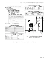
Table 2. Power Consumption.

Table 3. Torque Ratings.

Table 4. Actuator 90° Stroke Timing.

Table 5. Actuator Minimum Design Life.

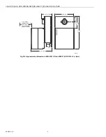
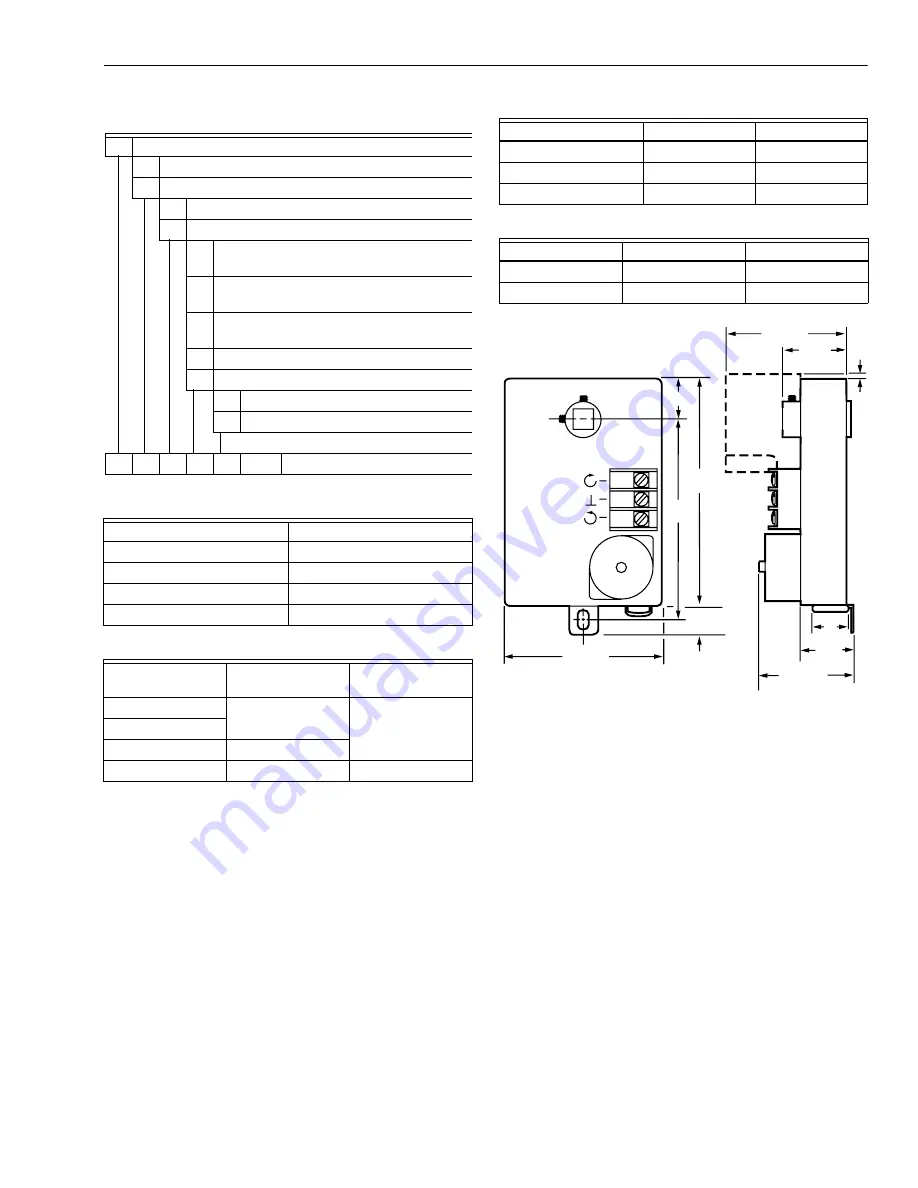
Fig. 1. Approximate dimensions of ML6161A,B,E 

and ML6174A,B,E DCA in in. (mm).

Fig. 1A. Approximate dimensions of ML7161, ML7174 DCA in in. (mm).

Model

Power Consumption

ML6161A,B,C,D

1.8 VA

ML7161A

4.8 VA

ML6174A,B

2.4 VA

ML7174A

5.4 VA

35 lb-in. DCA 

lb-in. (Nm)

70 lb-in. DCA 

lb-in. (Nm)

Running

35 (4)

70 (8)

Breakaway
Stall Minimum

45 (5)

Stall Maximum

70 (8)

130 (14)

Table 1. 35 lb-in. and 75 lb-in. DCA models.

ML

Motor Linkage

61

Floating Control

71

4-20 mA/2-10 Vdc Control

61

35 lb-in. (4 Nm), Non-Spring Return

74

70 lb-in. (8 Nm), Non-Spring Return

A

Includes output for feedback 

potentiometer.

B

Standard (includes minimum-position 

setscrews).

C

Includes output for feedback potentiometer 

and cover with conduit connections.

D

Includes cover with conduit connections.

E

Standard with European ratings.

1

Standard.

2

Includes declutch function.

ML 61 61 B

1

XXX Varies by model

At 50 Hz

At 60 Hz

90 Second Models

108 sec

90 sec

Three-Minute Models

216 sec

180 sec

Seven-Minute Models 504 sec

420 sec

35 lb-in. DCA

70 lb-in. DCA

Cycles

50,000

40,000

Repositions

1,500,000

1,500,000

1 (25)

M18016

CW

COM

CCW

OPTIONAL
AUXILIARY
SWITCH

11/16

(18)

3-3/8 (86)

4-1/4

(108)

4-7/8

(123)

2-7/8  (73)

1-11/16

(42)

1/8

(3)

1-5/16

(33)

7/8

(22)

2-1/2  (64)

Содержание ML6161 Series

Страница 1: ...spdt floating thermostats or two position control systems Two position control requires installation of the 201052B Auxiliary Switch FEATURES Selectable 45 60 or 90 stroke in both clockwise cw or counterclockwise ccw directions 0 to 30 minimum position adjustment cw or ccw direction on all models Magnetic coupling eliminates the need for mechanical stops Two field addable auxiliary switches Auxili...

Страница 2: ...58 kg Actuator Timing for 90 Stroke See Table 4 Mounting Mounts directly on 3 8 in to 1 2 in 10 to 13 mm round or square shaft Can be mounted with shaft in any position with two 1 4 in 6 mm 28 NF Allen screws Mini mum Shaft Length Required 1 3 4 in 45 mm Temperature Ratings Ambient 20 F to 125 F 18 C to 50 C Derated Timing to 20 F 29 C Shipping and Storage 20 F to 130 F 29 C to 54 C Humidity Ratin...

Страница 3: ...Linkage 61 Floating Control 71 4 20 mA 2 10 Vdc Control 61 35 lb in 4 Nm Non Spring Return 74 70 lb in 8 Nm Non Spring Return A Includes output for feedback potentiometer B Standard includes minimum position setscrews C Includes output for feedback potentiometer and cover with conduit connections D Includes cover with conduit connections E Standard with European ratings 1 Standard 2 Includes declu...

Страница 4: ...IRECT COUPLED ACTUATORS 63 2209 8 4 Fig 1B Approximate dimensions of ML6161C D and ML6174C D DCA in in mm M18018 5 7 8 149 1 13 16 46 1 25 3 5 8 92 1 13 16 46 3 IN 76 MM MINIMUM SPACING REQUIRED FOR REMOVING CONDUIT COVER 3 3 4 95 7 8 22 ...

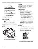
Страница 5: ... designed to open a damper or valve by driving the shaft in either the clockwise cw or counterclockwise ccw direction The actuator has a mounting tab on the bottom that secures it to a damper box or valve linkage When mounted correctly this tab allows the actuator to float without rotating relative to the shaft The tab is sized for 1 4 in screw or pin not included CAUTION Equipment Damage Hazard T...

Страница 6: ...gle of the damper opening is either 45 or 60 close the actuator using the manual declutch a Disengage the hub using the declutch lever see Manual Operation Declutch section b Rotate the hub until the actuator gear train passes the proper 45 or 60 setting Do not insert the pin until after the actuator passes this point c Release the declutch lever NOTE Dampers with 90 stroke do not require the rang...

Страница 7: ...ng 7 If resistance is met before the setscrew is fully inserted stop and review the initial setup procedures as detailed in steps 1 through 3 8 Determine the angle of minimum position required for the application With the setscrew fully inserted the minimum position is 30 With the setscrew fully out the minimum position is 0 9 Using the conversion of approximately 1 7 angular degrees per turn of t...

Страница 8: ... ends if necessary and connect to the CW COM and CCW terminals using Fig 11 through 14 Fig 16 through 20 or the control manufacturer instructions 5 Apply power to the actuator 6 After operational checkout replace the cover by reversing the procedure outlined in step 1 Fig 10 Conduit cover for ML6161C D and ML6174C D DCA Fig 11 ML6161 or ML6174 used with T87F in heating only or cooling only applica...

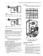
Страница 9: ...or body and the bracket is aligned over the screw hole 4 Insert the screw provided into the hole and fasten securely IMPORTANT Failure to follow the calibration procedures can result in improper resistance values at desired stroke Fig 15 ML6161A C ML6174A C with field addable potentiometer To Calibrate the 200976A C IMPORTANT Remove the range stop pins and minimum position setscrews prior to calib...

Страница 10: ...all thermostats The T641 is a mercury bulb floating control type thermostat designed for use with the seven minute model on pressure dependent systems see Fig 16 and 17 The T6984 is an electronic floating control thermostat designed for use with the 90 second and seven minute models see Fig 18 Fig 16 T641A controlling ML6161 or M6174 Actuator Fig 17 Minimum position set with auxiliary switch conta...

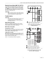
Страница 11: ...llel Make certain the total connected load does not exceed the current capacity of the input signal source CURRENT INPUT 4 TO 20 MA When using a current controller such as the W7600 wire the ML7161 ML7174 voltage input terminals Vdc and in parallel Use a bridging resistor in parallel with the 4 to 20 mA signal See Fig 20 for resistor values NOTE The actuator has 45 000 ohm impedance Fig 19 Spdt co...

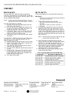
Страница 12: ...of the thermostat higher to determine if the wiring is correct 4 If no movement is observed check for the presence of 24 volts 5 If using the T641 Thermostat check that 24 volts are present between terminals C and Y during a call for cooling With proper wiring and 24 volts present the actuator should operate correctly 6 If not replace the actuator ML7161 ML7174 Check input impedance on the actuato...

Отзывы: