35 AND 70 LB-IN. NON-SPRING RETURN DIRECT COUPLED ACTUATORS
11
63-2209—8
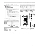
Rotation Reversal Switch (ML7161, ML7174)
Use the rotation reversal slide switch to reverse the actuator
rotation. The switch is located on the bottom of the actuator
housing (see Fig. 5). To change rotation to counterclockwise
(ccw)
, change the slide switch. In direct, 2 volts is fully
ccw and 10 volts is fully clockwise (cw); in reverse, 2 volts is
fully cw and 10 volts is fully ccw.
IMPORTANT
When reversing the rotation, make sure the switch is
fully to one side or the other. If the switch is left in the
middle, the actuator will not operate properly.
Parallel Actuators
IMPORTANT
Over time, parallel-driving actuators can become out
of sync with each other. Normally, driving all
actuators to the fully-open or fully-closed position
puts them back in sync.
ML6161, ML6174 Actuators
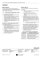
Using Fig. 19, parallel the CW, COM and CCW terminals.
Make certain the total connected load does not exceed the
current capacity of the controller or thermostat.
ML7161, ML7174 Actuators
VOLTAGE INPUT (2 TO 10 VDC)
Wire the (+Vdc) and (-) terminals of each actuator in parallel.
Make certain the total connected load does not exceed the
current capacity of the input signal source.
CURRENT INPUT (4 TO 20 MA)
When using a current controller (such as the W7600), wire the
ML7161, ML7174 voltage input terminals (+Vdc) and (-) in
parallel. Use a bridging resistor in parallel with the 4 to 20 mA
signal. See Fig. 20 for resistor values.
NOTE: The actuator has 45,000 ohm impedance.
Fig. 19. Spdt control of parallel ML6161
or ML6174 Actuators.
Fig. 20. 4-20 mA signal control of parallel
ML7161 or ML7174 Actuators.
1
1
R
C
Y
W
T641A THERMOSTAT
L1
(HOT)
24 VAC
POWER SUPPLY. PROVIDE DISCONNECT MEANS AND
OVERLOAD PROTECTION, AS REQUIRED. ENSURE THAT
EQUIPMENT TRANSFORMER IS CORRECTLY SIZED.
M18024
ML6161, ML6174
CW
COM
CCW
ML6161, ML6174
CW
COM
CCW
L2
L1
(HOT)
L1
(HOT)
L2
L2
1
2
3
3
3
2
2
1
ACTUATORS CAN USE COMMON TRANSFORMER;
SEPARATE POWER SUPPLY REQUIRED FOR W7600.
POWER SUPPLY. PROVIDE DISCONNECT MEANS AND
OVERLOAD PROTECTION AS REQUIRED. ASSURE THAT
EQUIPMENT TRANSFORMER IS SIZED CORRECTLY.
V1
V2
+
–
R
4-20 mA
ML7161, ML7174
ML7161, ML7174
ML7161, ML7174
V
–
T1
T2
V
–
T1
T2
V
–
T1
T2
W7600
1 ACTUATOR = 549 OHMS
2 ACTUATORS = 549 OHMS
3 ACTUATORS = 549 OHMS
4 ACTUATORS = 576 OHMS
5 ACTUATORS = 576 OHMS
6 ACTUATORS = 576 OHMS
7 ACTUATORS = 590 OHMS
8 ACTUATORS = 604 OHMS
9 ACTUATORS = 604 OHMS
10 ACTUATORS = 619 OHMS
1/2 WATT
M18025


