SYSTEM INSTALLATION MANUAL
KTR 2280A
Page 2-4
15 May 2017
© Honeywell International Inc. Do not copy without express permission of Honeywell.
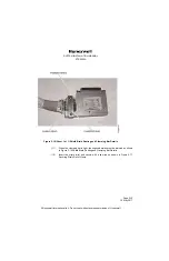
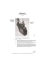
Connect the antenna to the COM unit with 50 ohm coaxial cable, keeping the cable length to a minimum and
avoiding sharp bends in the cable. Keep the COM antenna cable as far away from other antenna cables as
possible and do not bundle several cables together. Prepare the cable to the BNC connector as shown in Figure
2-18 Right Angle Connector Instruction Sheet
Use Dow-Corning DC-4, or equivalent, on both inside and outside of the connector and its mate as an effective
barrier against moisture and to prevent corrosion.
2.3.4.2 NAV Antennas
LIMITATIONS:
If radio is used for VDB installation, the total minimum installation loss must be 5 dB in NAV
antenna RF path. Installation loss includes the antenna gain and implementation loss from
antenna to MMDR.
The NAV antenna must be well removed from other antennas, projections, engines or propellers. It must have
a clear line of sight area if possible. The antenna must be mounted symmetrically with the center line of the
aircraft. Avoid running other coaxial cables and wires near the NAV antenna cable.
The VOR/LOC antenna with Glideslope is a two piece dipole with one part mounted on each side of the vertical
stabilizer. It must be installed on the upper section of the vertical stabilizer of single finned aircraft and be at least
28 inches (measured vertically) from the horizontal stabilizer.
On dual VOR/ILS installations, it is recommended that a splitter be used to divide signals from a single VOR/
LOC antenna into two or more receivers. Use double shielded cables to reduce interference to the receivers.
Prepare the cable to the BNC connector as shown in Figure 2-18 Right Angle Connector Instruction Sheet
2.3.4.3 ADF Antennas
The antenna installation will determine, to a large extent, whether the ADF will give optimum performance as
required. The KA 44B ADF Antenna contains both the loop and sense antennas. The following considerations
must be taken into account before selecting a location for the antenna:
CAUTION KEEP THE ANTENNA AT LEAST 4 FEET AWAY FROM DME OR TRANSPONDER ANTENNAS
TO MINIMIZE L-BAND INTERFERENCE. THE ANTENNA MUST BE MOUNTED WELL CLEAR
OF THE AIRCRAFT GENERATOR/ALTERNATOR AND WELL CLEAR OF ANY GENERATOR/
ALTERNATOR CABLES.
CAUTION: DO NOT ROUTE THE CABLES ALONG WITH HIGH POWER LEVEL TRANSMITTING
CABLES. DO NOT ROUTE THE CABLES WITH OR NEAR ALTERNATOR OR 400HZ CABLES.
MAKE SURE THAT THE CABLES DO NOT INTERFERE WITH ANY OF THE AIRCRAFT
CONTROL CABLES.
• Mount the antenna on the center line of the aircraft fuselage. Failure to do so can result in
excessive Q.E. error.
• If the antenna is to be top mounted, select a location where shadowing from the wings, etc., is
minimized.
• The antenna must be well removed from any projections such as engines and propellers, as well
as landing gear doors, access doors or other openings which will break the ground plane for the
antenna.


