SYSTEM INSTALLATION MANUAL
KTR 2280A
Page 2-14
15 May 2017
© Honeywell International Inc. Do not copy without express permission of Honeywell.
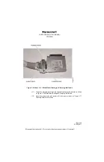
Figure 2-15 (Sheet 1 of 1) Assembly Details
(3) Crimp pins or sockets onto the wires.
(4) Insert the pins or sockets into the connector. When using oversized power and
ground contacts, ensure heat shrink tubing is used to cover exposed ends of
contacts.
(5) Place the backshell over the wire bundle.
(6) Attach the connector to the backshell.
(7) Insert the shield braid into the slot in the backshell cover
(8) Attach the backshell cover to the backshell with the screws provided.
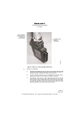
(9) Dress the twisted shields as shown in Figure 2-16 Shield Braid Routing and
Clamping Bar Details. Do not allow twisted shields to cross over each other.
Tighten the clamping bar to secure the braids and provide a reliable electrical
ground.


