background image

SYSTEM INSTALLATION MANUAL

KTR 2280A

Page 2-5 

15 May 2017

© Honeywell International Inc. Do not copy without express permission of Honeywell.

•                     Use the template included in the installation kit to mark the mounting holes on the aircraft fuselage.

•                     Drill and/or punch the required holes.

•                     Use a piece of fine sandpaper or emery cloth to sand the area on the fuselage skin on which the


backup plate is to be mounted.

•                     Apply Alumiprep No. 33, PN 016-01127-0000, to both the inside area of the fuselage and the back


of the doubler plate, following the directions on the container to cleanse the metal of any residue.

•                     Apply Alodine No. 1001, PN 016-00128-0000, to both locations following the directions on the


container. This is used to ensure good bonding and prevent oxidation.

•                     Refer to the installation manual and mount the antenna as shown. First rivet the doubler plate in


place. It is imperative that the doubler plate make a good ground plane contact with the inside of 
the aircraft skin.

•                     Prepare the ADF RF cable as shown in Figure 2-1 thru Figure 2-11 Quadraxial Cable Preparation. 

Note that the cable provided can be cut to length as required for the installation.

2.3.5               KTR 2280A Wiring and Cable Installation

2.3.5.1                KTR 2280A Interconnection and Cable Harness Fabrication

The KTR 2280A MMDR receives primary power from the aircraft power source. A typical interface is shown in


Figure 2-24 KTR 2280A Interconnect Diagram. Aircraft specific interfaces with more details are provided in


separate EB or Installation Drawings.

The length of the wires to parallel pins must be approximately the same length, so that the best distribution of 
current can be effected. Honeywell recommends that all wires, including spares, as provided with the


interconnect definition information be included in the fabrication of the wiring harness. However; if full wiring is


not desired, the installer must ensure that the minimum wiring requirements for the features and functions to be


used have been incorporated.

When cables are installed in the aircraft, they must be supported firmly enough to prevent movement and must 
be carefully protected against chafing. Additional protection must also be provided in all locations where the


cable can be subjected to chafing.

In wire bundles, the cabling must not be tied tightly together as this tends to increase the possibility of noise


pickup and similar interference. When routing cables through the aircraft the cables must cross high level RF


lines at right angles.

Prior to installing any equipment, make a continuity check of all wires and cables associated with the system. 
Then apply power and check for proper voltages at system connectors, and then remove power before


completing the installation.

The following guidelines are recommended:

(1)                          The  installing  facility will supply and fabricate all external cables. The required connec-

tors are supplied as part of the installation kit (Refer to 1.4.1 KTR 2280A Installation


Kit).

Содержание KTR 2280A

Страница 1: ...nd authorized for export only to the country of ultimate destination for use by the ultimate consignee or end user s herein identified They may not be resold transferred or otherwise disposed of to any other country or to any person other than the authorized ultimate consignee or end user s either in their original form or after being incorporated into other items without first obtaining approval ...

Страница 2: ...e Grant If you are a party to an applicable written agreement with Honeywell relating to the repair or maintenance of the subject Honeywell Product subject to your compliance with the terms and conditions of this License Agreement Honeywell hereby grants you and you accept a limited personal non transferrable non exclusive license to use these Materials only in accordance with that agreement If yo...

Страница 3: ...l be assignable or transferable in insolvency proceedings by merger by operation of law by purchase by change of control or otherwise by you without Honeywell s written consent 7 Copies of Materials Unless you have the express written permission of Honeywell you may not make or permit making of copies digital or printed of the Materials You agree to return the Materials and any such copies thereof...

Страница 4: ...RECOMMENDED BY THE MANUFACTURER OR SUPPLIER FAILURE TO OBEY THE MANUFACTURERS OR SUPPLIERS RECOMMENDATIONS CAN RESULT IN PERSONAL INJURY OR DISEASE This publication describes physical and chemical processes which can make it necessary to use chemicals solvents paints and other commercially available materials The user of this publication must get the Material Safety Data Sheets OSHA Form 174 or eq...

Страница 5: ...nternational Inc Do not copy without express permission of Honeywell Copyright Notice Copyright 2017 Honeywell International Inc All rights reserved Honeywell is a registered trademark of Honeywell International Inc All other marks are owned by their respective companies ...

Страница 6: ...Page T 6 15 May 2017 SYSTEM INSTALLATION MANUAL KTR 2280A Honeywell International Inc Do not copy without express permission of Honeywell Blank Page ...

Страница 7: ... 2280A MULTI MODE DIGITAL RADIO SIM PUBLICATION No D201610000049 ISSUED FOR USE IN SUPPORT OF THE FOLLOWING Table TI 1 shows the applicable components Revision History Table TI 2 shows the revision history of this SIM Table TI 1 Applicable Components Component PN Nomenclature 069 01039 0101 KTR 2280A Multi Mode Digital Radio Table TI 2 Revision History Revision Number Revision Date 0 15 May 2017 ...

Страница 8: ...Page TI 2 15 May 2017 SYSTEM INSTALLATION MANUAL KTR 2280A Honeywell International Inc Do not copy without express permission of Honeywell Blank Page ...

Страница 9: ... RECORD OF REVISIONS For each revision write the revision number revision date date put in the manual and your initials in the applicable column NOTE Refer to the Revision History in the TRANSMITTAL INFORMATION section for revision data Revision Number Revision Date Date Put In Manual By Revision Number Revision Date Date Put In Manual By ...

Страница 10: ...Page RR 2 15 May 2017 SYSTEM INSTALLATION MANUAL KTR 2280A Honeywell International Inc Do not copy without express permission of Honeywell Blank Page ...

Страница 11: ...each temporary revision put the applicable data in the record columns on this page Definition of Status column A TR may be active incorporated or deleted Active is entered by the holder of the manual Incorporated means a TR has been incorporated into the manual and includes the revision number of the manual when the TR was incorporated Deleted means a TR has been replaced by another TR a TR number...

Страница 12: ...Page RTR 2 15 May 2017 SYSTEM INSTALLATION MANUAL KTR 2280A Honeywell International Inc Do not copy without express permission of Honeywell Blank Page ...

Страница 13: ... 2017 INTRO 6 15 May 2017 Section 1 General Information 1 1 15 May 2017 1 2 15 May 2017 1 3 15 May 2017 1 4 15 May 2017 1 5 15 May 2017 1 6 15 May 2017 1 7 15 May 2017 1 8 15 May 2017 Section 2 Installation 2 1 15 May 2017 2 2 15 May 2017 2 3 15 May 2017 2 4 15 May 2017 2 5 15 May 2017 2 6 15 May 2017 2 7 15 May 2017 2 8 15 May 2017 2 9 15 May 2017 2 10 15 May 2017 2 11 15 May 2017 2 12 15 May 201...

Страница 14: ... 15 May 2017 2 47 15 May 2017 2 48 15 May 2017 2 49 15 May 2017 2 50 15 May 2017 2 51 15 May 2017 2 52 15 May 2017 Section 3 Operation 3 1 15 May 2017 3 2 15 May 2017 3 3 15 May 2017 3 4 15 May 2017 Appendix A Environmental Qualification Forms A 1 15 May 2017 A 2 15 May 2017 A 3 15 May 2017 A 4 15 May 2017 A 5 15 May 2017 A 6 15 May 2017 A 7 15 May 2017 A 8 15 May 2017 Appendix B Deviations B 1 15...

Страница 15: ...2 B Honeywell Aerospace Contact Team INTRO 2 3 References INTRO 2 A Honeywell Vendor Publications INTRO 2 B Other Publications INTRO 2 4 Acronyms and Abbreviations INTRO 3 A General INTRO 3 SECTION 1 GENERAL INFORMATION 1 1 INTRODUCTION 1 1 1 2 EQUIPMENT DESCRIPTION 1 1 1 3 TECHNICAL CHARACTERISTICS 1 1 1 3 1 KTR 2280A Technical Characteristics 1 1 1 3 2 KA 44B Technical Characteristics 1 3 1 4 UN...

Страница 16: ... Harness Fabrication 2 5 2 3 5 2 Taylor Backshell Instructions 2 10 2 3 5 3 Primary Power and Circuit Breaker Requirements 2 19 2 3 5 4 Connectors 2 19 2 3 5 5 Crimp Tool Information 2 22 2 4 POST INSTALLATION CHECKS 2 45 2 4 1 KTR 2280A MMDR Post Installation Inspection and Ground Test 2 45 2 4 1 1 Inspection 2 45 2 4 1 2 Ground Tests 2 46 2 4 2 KTR 2280A Post Installation Flight Tests 2 48 2 4 2...

Страница 17: ...reparation 2 9 Figure 2 10 Quadrex Cable Preparation 2 9 Figure 2 11 Connector Assembly 2 10 Figure 2 12 Taylor Backshell Instructions 2 11 Figure 2 13 Backshell Assembly Exploded View 2 12 Figure 2 14 Assembly Details 2 13 Figure 2 15 Assembly Details 2 14 Figure 2 16 Shield Braid Routing and Clamping Details 2 15 Figure 2 17 Securing Strain Relief Clamp 2 16 Figure 2 18 Right Angle Connector Ins...

Страница 18: ...s 1 2 Table 1 2 KA 44B Technical Characteristics 1 3 Table 2 1 KTR 2280A Backshell Hardware 2 12 Table 2 2 J1 Pin Functions 2 19 Table 2 3 Antenna Connector Functions 2 21 Table 2 4 KA 44B Pin Functions 2 22 Table 2 5 Crimp Tools and Accessories 2 22 Table 2 6 Inspection Check Procedure 2 45 Table 2 7 Unit Parameters 2 49 Table 2 8 ARINC 429 Output Labels 2 50 Table 2 9 ARINC 429 Input Labels 2 51...

Страница 19: ...rocedure which if not obeyed can cause damage to the equipment A NOTE gives data not commands The NOTE helps personnel when they do the related instruction 5 Warnings and cautions go before the applicable paragraph or step Notes follow the applicable paragraph or step B Observance of Manual Instructions 1 Make sure that you carefully obey all safety quality operation and shop procedures for the un...

Страница 20: ...der a publication To tell Honeywell of a possible data error in a publication B Honeywell Aerospace Contact Team 1 If you do not have access to the Honeywell Technical Publications Website or if you need to speak to personnel about non Technical Publication matters the Honeywell Aerospace Contact Team gives 24 7 customer service to Air Transport Regional Business General Aviation and Defense Space...

Страница 21: ...ices Metric available from any military standards database MIL STD 1686 Electrostatic Discharge Control Program for Protection of Electrical and Electronic Parts Assemblies and Equipment Excluding Electrically Initiated Explosive Devices Metric available from any military standards database 4 Acronyms and Abbreviations A General 1 The abbreviations are used in agreement with ASME Y14 38 2 Acronyms...

Страница 22: ...g bulletin ECCN export control classification number ELT emergency locator transmitter ESDS electrostatic discharge sensitive ETSO European Technical Standard Order FAA Federal Aviation Administration FCC Federal Communications Commission GMT Greenwich mean time GND ground GPO Government Printing Office GRY grey GS glidescope HIRF high intensity radiated fields Hz hertz IEC International Electrote...

Страница 23: ...program PN part number POA plain old aircraft communications addressing and reporting system PTT push to talk PWR power QE quadrantal error REV revision RF radio frequency RTCA Radio Technical Commission for Aeronautics RX receiver SIM system installation manual SNR signal to noise ratio STC supplemental type certificate TC type certificate TSO technical standard order TX transmiter UTC universal ...

Страница 24: ...ay 2017 SYSTEM INSTALLATION MANUAL KTR 2280A Honeywell International Inc Do not copy without express permission of Honeywell VSWR voltage standing wave ratio W watt List of Acronyms and Abbreviations Cont Term Full Term ...

Страница 25: ... controlled by other LRUs which will send control information to the KTR 2280A through ARINC 429 data Some outputs from the KTR 2280A are in digital formats and sent to other LRUs through ARINC 429 Other outputs are more traditional analog outputs The six receivers and their modes of operation are as follows The NAV receiver operates in one of three modes as dynamically controlled by the system in...

Страница 26: ... C41d ETSO 2C41d DO 179 for Class A and ED 51 STUCK MICROPHONE TSO 128a ETSO 2C128 DO 207 and ED 67 VDB TSO C162a and DO 253C VDL MODE 2 TRANSCEIVER TSO C160a DO 281B and ED 92B for Class YF7 TSO ETSO DEVIATIONS Refer to APPENDIX B NON TSO FUNCTIONS TRANSCEIVER ACARS Mode A SOFTWARE QUALIFICATION DO 178B Level B HARDWARE QUALIFICATION DO 254 Level B ENVIRONMENTAL CATEGORIES Refer to APPENDIX A PHY...

Страница 27: ...IVE NOMINAL 19 Watt 0 7 A at 27 5 V RECEIVE NOMINAL W 10 TRANSMIT 33 Watt 1 19 A at 27 5 V RECEIVE NOMINAL W 100 TRANSMIT 154 Watt 5 6 A at 27 5 V RECEIVE MAXIMUM 28 Watt 1 02 A at 27 5 V RECEIVE MAXIMUM W 10 TRANSMIT 43 Watt 1 57 A at 27 5 V RECEIVE MAXIMUM W 100 TRANSMIT 179 Watt 6 5 A at 27 5 V SPECIFICATION CHARACTERISTIC TSO COMPLIANCE Refer to APPENDIX A ENVIRONMENTAL SPECIFICATIONS Refer to...

Страница 28: ...T FEM 22 W 20 AWG CRMP BARREL EA 6 00 047 11179 0004 STAIN RELIEF CLAMP 220 EA 1 00 047 11310 0004 RACK W FINISH EA 1 00 057 05944 0085 KTR 2280A KIT TSO LABEL EA 1 00 073 01140 0003 BACKPLATE W HARDWARE EA 1 00 073 01141 0002 CONNECTOR HOOD SUB D 25 90 DEG W FINISH EA 1 00 073 01142 0002 CONN HOOD COVER W FINISH EA 1 00 076 03189 0001 SCREW 100DEG FHP 2 56 X 3 8 SPECIAL EA 5 00 088 03559 0001 FAN...

Страница 29: ... INSTALL KIT 48 FT MMDR KA 44B DO 160D C SYM BOL PART NO FIND NO DESCRIPTION UM 0020 030 00101 0000 PANEL MNT PLUG EA 1 00 057 02259 0000 ANT MTG TEMPLATE EA 1 00 057 05944 0074 KA 44B KIT TSO LABEL EA 1 00 076 01042 0001 FERRULE W F EA 1 00 090 00019 0007 RING RTNR 438 EA 1 00 091 00031 0005 NY CA CLAMP 312 EA 1 00 155 05334 0000 INST DWG KA44B RF 0 00 200 02586 0020 ANT CBL ASSY 48FT KA 44B DO 1...

Страница 30: ...0 3 Alodine No 1001 PN 016 00128 0000 4 Dow Corning DC 4 or equivalent 1 6 LICENSING REQUIREMENTS The KTR 2280A meets CFR Title 47 Part 2 15 and 87 FCC Approvals for all radio equipment For non US registered aircraft follow applicable licensing requirements as required This device complies with Industry Canada s license exempt RSSs Operation is subject to the following two conditions This device c...

Страница 31: ...erformance test information All maintenance must be performed by a Honeywell approved repair center 14 CFR Part 23 1529 and 25 1529 Instructions for Continued Airworthiness is met per the following instructions The removal of the equipment is on the condition of failure There is no required periodic maintenance for the KTR 2280A NOTE Upon completion of maintenance or repair the post installation c...

Страница 32: ...SYSTEM INSTALLATION MANUAL KTR 2280A Page 1 8 15 May 2017 Honeywell International Inc Do not copy without express permission of Honeywell Blank Page ...

Страница 33: ...RF cabling and antennas to determine the acceptability 2 2 UNPACKING and INSPECTING EQUIPMENT Exercise extreme care when unpacking the equipment Make a visual inspection of the unit for evidence of damage during shipment If a claim for damage is to be made save the shipping container to substantiate the claim The claim must be promptly filed with the transportation company It would be advisable to...

Страница 34: ...m other antenna projections the engine s and propeller s It must also be well removed from landing gear doors access doors or other openings which will break the ground plane for the antenna s On metal skinned aircraft the antenna s must be bonded to the surface of the aircraft in a fore to aft location that provides the flattest ground plane On composite aircraft the antenna s must be located at ...

Страница 35: ...ted as far away as possible from an ELT antenna to prevent distortion of the radiated pattern and to prevent radiated broadband noise from the ELT when excited by the COM transmissions Radiated broadband noise from an ELT is a common cause of COM to COM and COM to NAV interference Mounting one antenna on top of the fuselage at the highest location to ensure a good radiation pattern and the other o...

Страница 36: ...nned aircraft and be at least 28 inches measured vertically from the horizontal stabilizer On dual VOR ILS installations it is recommended that a splitter be used to divide signals from a single VOR LOC antenna into two or more receivers Use double shielded cables to reduce interference to the receivers Prepare the cable to the BNC connector as shown in Figure 2 18 Right Angle Connector Instructio...

Страница 37: ...igure 2 24 KTR 2280A Interconnect Diagram Aircraft specific interfaces with more details are provided in separate EB or Installation Drawings The length of the wires to parallel pins must be approximately the same length so that the best distribution of current can be effected Honeywell recommends that all wires including spares as provided with the interconnect definition information be included ...

Страница 38: ...tion must be provided in all locations where the cables can be subject to chafe Shields on shielded wires must be grounded in accordance with the system in terconnection information 5 Shields must be carried through any obstruction through a thru bulkhead connector If shielding cannot be carried through by use of a bulkhead connector pin precautions must be taken to ensure each segment of the shie...

Страница 39: ...on 4 Tin the exposed shield of the middle coax With a cutting tool score the tinned shield around the entire circumference as shown in Figure 2 4 Figure 2 4 Sheet 1 of 1 Quadraxial Cable Preparation 5 Carefully break loose the tinned middle coax shield and slide it off This will expose the center coax insulation as shown in Figure 2 5 Figure 2 5 Sheet 1 of 1 Quadraxial Cable Preparation ...

Страница 40: ...nter shield as shown in Figure 2 6 Figure 2 6 Sheet 1 of 1 Quadraxial Cable Preparation 7 Tin the shield for the center coax as shown in Figure 2 7 Figure 2 7 Sheet 1 of 1 Quadraxial Cable Preparation 8 Measure back from the end of the cable 0 30 inch 7 6 mm and score the center shield with a cutting tool around the full circumference as shown in Figure 2 8 Figure 2 8 Sheet 1 of 1 Quadraxial Cable...

Страница 41: ...iddle shield stub to prevent possible shorts to the outer shield as shown in Figure 10 Figure 2 10 Sheet 1 of 1 Quadraxial Cable Preparation 11 Connector Assembly Install the ferrule over the center shield and solder Slip the cable into the connector housing as shown in Figure 2 11 Solder the center conductor to the center terminal Pull up the outer shield and solder to the bottom stem Install shr...

Страница 42: ...or Backshell Instructions A General Information 1 Taylor Backshells are a proprietary Honeywell design developed to expedite cable harness fabrication while ensuring that HIRF and lightning performance goals are met A typical backshell is shown in Figure 2 12 Typical Taylor Backshell Figure 2 13 Backshell Assembly Exploded View provides an exploded view of the backshell Table 2 1 KTR 2280A Backshe...

Страница 43: ...SYSTEM INSTALLATION MANUAL KTR 2280A Page 2 11 15 May 2017 Honeywell International Inc Do not copy without express permission of Honeywell Figure 2 12 Sheet 1 of 1 Typical Taylor Backshell Instructions ...

Страница 44: ...et 1 of 1 Backshell Assembly Exploded View B Backshell Wiring 1 Strip the outer jacket of the twisted pair as shown in Figure 2 14 Assembly Details Trim the shield braid to 1 25 inch 31 75 mm length and then comb out Table 2 1 KTR 2280A Backshell Hardware Connector Type PN Backshell Cover Cover Screws Bar Clamp Assy Strain Relief Clamp 44 pin right angle custom 073 01141 0002 073 01142 0002 076 03...

Страница 45: ...ell the braid The braids from two twisted pairs can be twisted together to maintain the proper diameter for the twisted braid Figure 2 14 Sheet 1 of 1 Assembly Details 2 If installing a single twisted pair the combed braid must be folded back on itself and twisted to form the proper diameter bundle Refer to Figure 2 15 Assembly Details ...

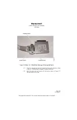
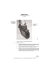
Страница 46: ...ure heat shrink tubing is used to cover exposed ends of contacts 5 Place the backshell over the wire bundle 6 Attach the connector to the backshell 7 Insert the shield braid into the slot in the backshell cover 8 Attach the backshell cover to the backshell with the screws provided 9 Dress the twisted shields as shown in Figure 2 16 Shield Braid Routing and Clamping Bar Details Do not allow twisted...

Страница 47: ...f Honeywell Figure 2 16 Sheet 1 of 1 Shield Braid Routing and Clamping Bar Details 11 When the clamping bar is tight the exposed braids must be trimmed as shown in Figure 2 16 Shield Braid Routing and Clamping Bar Details 12 Insert the strain relief and secure with a tie wrap as shown in Figure 2 17 Securing Strain Relief Clamp ...

Страница 48: ...llow the wire to lay in the backshell without straining the wires 2 Grounding Taylor Backshells have an external tapped hole that can be used to attach a ground strap This can be used at the installer s discretion 3 Shell Aperture When the strain relief is tightened against the wire bundle ensure that there are no large openings in the shell back and that the wires are held securely A different si...

Страница 49: ...YSTEM INSTALLATION MANUAL KTR 2280A Page 2 17 15 May 2017 Honeywell International Inc Do not copy without express permission of Honeywell Figure 2 18 Sheet 1 of 1 Right Angle Connector Instruction Sheet ...

Страница 50: ...SYSTEM INSTALLATION MANUAL KTR 2280A Page 2 18 15 May 2017 Honeywell International Inc Do not copy without express permission of Honeywell Blank Page ...

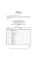
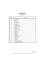
Страница 51: ... be found in the system installation manual and or EB for a specific installation 2 3 5 4 Connectors Figure 2 19 Sheet 1 of 1 KTR 2280A Mating Connector Front View Table 2 2 J1 Pin Functions Pin No Pin Name Description 1 O A429 Out1 A 2 O ADF Loop Enable OUT 3 I Test 4 I Unit Pos PGM 1 5 I Unit Pos PGM 2 6 I COM TX Interlock IN 7 I COM MIC Key IN 8 O RS 422 RX A 9 O RS 422 RX B 10 I RS 422 TX A 11...

Страница 52: ...urn 1 25 I DC Power 2 IN 26 I Emergency Channel 27 I COM MIC Audio IN 28 I A429 IN3 B 29 O NAV Audio LO OUT 30 O NAV Audio HI OUT 31 O ADF MOD 90 OUT 32 O A429 Out2 B 33 O MMDS FAN 5V OUT 34 I A429 IN1 B 35 O A429 OUT3 B 36 I A429 IN2 B 37 I Pgm Pin Common 38 O ADF ANT PWR OUT 39 I DC Power 1 IN 40 I DC Return 2 41 I Download 42 I O VDL Interlock IN OUT 43 O COM Audio Sidetone LO OUT 44 O COM Audi...

Страница 53: ...ermission of Honeywell Table 2 3 Antenna Connector Functions Figure 2 20 Sheet 1 of 1 KA 44B Mating Connector Front View Part of Antenna Cable Assembly PN 200 02586 0020 Connector Pin I O Description J101 1 I O COM RF J102 1 I ADF RF IN J103 1 I NAV RF IN J104 1 I Glideslope RF IN Note indicates the Pin is active GND ...

Страница 54: ... Information Table 2 5 Crimp Tools and Accessories PIN I O SIGNAL NAME 1 I ANTENNA POWER 2 I LOOP ENABLE 3 O RF INPUT 4 I ADF MOD 90 Out 5 I ADF MOD 0 Out 6 NO CONNECTION 7 GROUND 8 INNER SHIELD 9 MIDDLE OUTER SHIELD Crimp Tool Honeywell PN 005 02012 0021 Positronic 9507 or equivalent Positioner Positronic 9502 3 or equivalent Insertion Extraction Tool Positronic 4811 2 0 0 or equivalent ...

Страница 55: ...TALLATION MANUAL KTR 2280A Page 2 23 15 May 2017 Honeywell International Inc Do not copy without express permission of Honeywell Figure 2 21 Sheet 1 of 4 KTR 2280A Installation Drawing Dwg No 155 06081 0000 Rev N ...

Страница 56: ...SYSTEM INSTALLATION MANUAL KTR 2280A Page 2 24 15 May 2017 Honeywell International Inc Do not copy without express permission of Honeywell Blank Page ...

Страница 57: ...TALLATION MANUAL KTR 2280A Page 2 25 15 May 2017 Honeywell International Inc Do not copy without express permission of Honeywell Figure 2 21 Sheet 2 of 4 KTR 2280A Installation Drawing Dwg No 155 06081 0000 Rev N ...

Страница 58: ...SYSTEM INSTALLATION MANUAL KTR 2280A Page 2 26 15 May 2017 Honeywell International Inc Do not copy without express permission of Honeywell Blank Page ...

Страница 59: ...TALLATION MANUAL KTR 2280A Page 2 27 15 May 2017 Honeywell International Inc Do not copy without express permission of Honeywell Figure 2 21 Sheet 3 of 4 KTR 2280A Installation Drawing Dwg No 155 06081 0000 Rev N ...

Страница 60: ...SYSTEM INSTALLATION MANUAL KTR 2280A Page 2 28 15 May 2017 Honeywell International Inc Do not copy without express permission of Honeywell Blank Page ...

Страница 61: ...TALLATION MANUAL KTR 2280A Page 2 29 15 May 2017 Honeywell International Inc Do not copy without express permission of Honeywell Figure 2 21 Sheet 4 of 4 KTR 2280A Installation Drawing Dwg No 155 06081 0000 Rev N ...

Страница 62: ...SYSTEM INSTALLATION MANUAL KTR 2280A Page 2 30 15 May 2017 Honeywell International Inc Do not copy without express permission of Honeywell Blank Page ...

Страница 63: ...LATION MANUAL KTR 2280A Page 2 31 15 May 2017 Honeywell International Inc Do not copy without express permission of Honeywell Figure 2 22 Sheet 1 of 1 KA 44B Outline and Mounting Drawing Dwg No 155 05334 0000 Rev AC ...

Страница 64: ...SYSTEM INSTALLATION MANUAL KTR 2280A Page 2 32 15 May 2017 Honeywell International Inc Do not copy without express permission of Honeywell Blank Page ...

Страница 65: ...LATION MANUAL KTR 2280A Page 2 33 15 May 2017 Honeywell International Inc Do not copy without express permission of Honeywell Figure 2 23 Sheet 1 of 1 KA 44B Outline and Mounting Drawing Dwg No 155 05334 0010 Rev AD ...

Страница 66: ...SYSTEM INSTALLATION MANUAL KTR 2280A Page 2 34 15 May 2017 Honeywell International Inc Do not copy without express permission of Honeywell Blank Page ...

Страница 67: ...STALLATION MANUAL KTR 2280A Page 2 35 15 May 2017 Honeywell International Inc Do not copy without express permission of Honeywell Figure 2 24 Sheet 1 of 5 KTR 2280A Interconnect Diagram Dwg No 155 01835 0000 Rev ...

Страница 68: ...SYSTEM INSTALLATION MANUAL KTR 2280A Page 2 36 15 May 2017 Honeywell International Inc Do not copy without express permission of Honeywell Blank Page ...

Страница 69: ...STALLATION MANUAL KTR 2280A Page 2 37 15 May 2017 Honeywell International Inc Do not copy without express permission of Honeywell Figure 2 24 Sheet 2 of 5 KTR 2280A Interconnect Diagram Dwg No 155 01835 0000 Rev ...

Страница 70: ...SYSTEM INSTALLATION MANUAL KTR 2280A Page 2 38 15 May 2017 Honeywell International Inc Do not copy without express permission of Honeywell Blank Page ...

Страница 71: ...STALLATION MANUAL KTR 2280A Page 2 39 15 May 2017 Honeywell International Inc Do not copy without express permission of Honeywell Figure 2 24 Sheet 3 of 5 KTR 2280A Interconnect Diagram Dwg No 155 01835 0000 Rev ...

Страница 72: ...SYSTEM INSTALLATION MANUAL KTR 2280A Page 2 40 15 May 2017 Honeywell International Inc Do not copy without express permission of Honeywell Blank Page ...

Страница 73: ...TION MANUAL KTR 2280A Page 2 41 15 May 2017 Honeywell International Inc Do not copy without express permission of Honeywell Blank Page Figure 2 24 Sheet 4 of 5 KTR 2280A Interconnect Diagram Dwg No 155 01835 0000 Rev ...

Страница 74: ...SYSTEM INSTALLATION MANUAL KTR 2280A Page 2 42 15 May 2017 Honeywell International Inc Do not copy without express permission of Honeywell Blank Page ...

Страница 75: ...STALLATION MANUAL KTR 2280A Page 2 43 15 May 2017 Honeywell International Inc Do not copy without express permission of Honeywell Figure 2 24 Sheet 5 of 5 KTR 2280A Interconnect Diagram Dwg No 155 01835 0000 Rev ...

Страница 76: ...SYSTEM INSTALLATION MANUAL KTR 2280A Page 2 44 15 May 2017 Honeywell International Inc Do not copy without express permission of Honeywell Blank Page ...

Страница 77: ...e not exposed to rough or sharp surfaces 2 System Interwiring Check To check the aircraft and MMDR system interconnections proceed as follows a Check that all cables and interwiring are installed in accordance with the interwiring and cable harness fabrication instructions refer to paragraph 2 3 5 1 KTR 2280A Interconnection and Ca ble Harness Fabrication b Using the applicable interconnection inf...

Страница 78: ...the metallic surface the antenna is bonded to Note that the committees that wrote the Minimum Operation Performance Standards to which the VHF COM system is TSO d are aware of this characteristic They have established that transmitter power for a 16 W minimum transmitter must not drop below 8 0 W into a 2 1 VSWR and 6 4 W into a 3 1 VSWR Refer to RTCA DO 186B and Eurocae ED 23C 2 Post Installation...

Страница 79: ...s with this step could also be due to the airfield location where the QE alignment procedure is being performed if that location is not magnetically clean 8 Using the aircraft s directional gyro or magnetic compass as a guide rotate the aircraft another 45 to the left so that the magnetic heading is now 135 less than the value found in Step 2 9 Record the number of degrees by which the ADF bearing...

Страница 80: ...tep 20 into the KTR 2280A Parameter table per 2 5 KTR 2280A INSTALLATION PARAMETER MODIFICATIONS 22 Recheck the relative bearings abd readjust the QE compensation as necessary to split the error at the quadrantal points 45 135 225 and 315 to obtain the lowest pos sible error b Operational Checks The following operational checks are to verify proper operation of the ADF function of the KTR 2280A an...

Страница 81: ...the unit installation NOTE KTR 2280A units sent to the factory for repair will be returned to service with their factory defaults reset as shown in Table 2 7 Unit Parameters The method for setting these parameters is a function of the specific installed system and the user interface used for personality module settings Refer to the appropriate STC Installation Manual for specific instructions The ...
Страница 82: ...both channels Table 2 8 ARINC 429 Output Labels Function Label Parameter Interval ms NAV 034 VOR ILS Frequency 200 053 VOR ILS Standby Preset Frequency 200 173 Localizer Deviation 100 174 Glideslope Deviation 100 222 VOR Bearing 100 242 VOR ILS Station Ident Characters 1 2 200 244 VOR ILS Station Ident Characters 3 4 200 265 VOR ILS Volume 200 COM 030 VHF COM Frequency 200 047 VHF Aux Guard COM Fr...

Страница 83: ...arameter Interval ms NAV 034 Set VOR ILS Frequency 200 053 Set VOR ILS Standby Preset Frequency 200 265 Set VOR ILS Volume 200 COM 030 Set VHF COM Frequency 200 047 Set VHF Aux Guard COM Frequency 200 052 Set VHF COM Standby Preset Frequency 200 263 Set VHF Aux Guard COM Volume 200 266 Set VHF COM Volume 200 ADF 032 Set ADF Frequency 200 262 Set ADF Volume 200 CLOCK 150 GMT UTC 1000 260 Date 1000 ...

Страница 84: ...rol 1000 VDB 033 Landing Mode Frequency 200 VDL 172 System Address label 1000 214 Aircraft ICAO Address 1 1000 216 Aircraft ICAO Address 2 1000 251 Williamsburg BOP VDR 1 Burst 252 Williamsburg BOP VDR 2 Burst 253 Williamsburg BOP VDR 3 Burst 270 Apex CMU Status Word 1 1000 276 Apex CMU Status Word 2 1000 276 VDR Mode Command 500 Function Label Parameter Interval ms ...

Страница 85: ...nly when a volume change is made C RX TX Annunciators Some display means indicate when the radio is transmitting TX Annunciator and when the radio is receiving RX Annunciator This is keyed by the squelch status The KTR 2280A outputs the RX status and TX status on the high speed ARINC 429 label 267 having a 5 Hz update rate D Squelch Disable Control Normally a pushbutton that cycles between Squelch...

Страница 86: ...r VDB mode selection This label only occurs when a mode change is made 3 1 3 ADF Controls and Displays A Frequency Selectors An active frequency channel and a standby frequency channel selector A swap or flip flop button may be available for swapping the active and standby frequencies The KTR 2280A responds to high speed ARINC 429 label 032 for frequency selection This label only occurs when a fre...

Страница 87: ...cate with the ground stations on the same frequency The data link service and management protocol includes procedures to establish maintain and hand off an air ground link and ensure error free delivery of messages The network access protocol is the interface between users and the Mode 2 air ground link service providers As in Mode A only the physical layer and channel access protocols are perform...

Страница 88: ...rough the same high speed ARINC 429 interface used to exchange downlink and uplink AOA or ATN messages The CMF also dynamically controls the switching between Mode A and Mode 2 operation subject to available coverage Since the VDL Mode 2 data rate and modulation scheme differ from those used in Mode A separate VHF frequencies and ground based VHF equipment must be used to give POA and AOA ATN serv...

Страница 89: ...EM INSTALLATION MANUAL KTR 2280A Page A 1 15 May 2017 Honeywell International Inc Do not copy without express permission of Honeywell APPENDIX A KTR 2280A MMDR TRANSCEIVER ENVIRONMENTAL QUALIFICATION FORMS ...

Страница 90: ...Page A 2 15 May 2017 SYSTEM INSTALLATION MANUAL KTR 2280A Honeywell International Inc Do not copy without express permission of Honeywell Blank Page ...

Страница 91: ...SYSTEM INSTALLATION MANUAL KTR 2280A Page A 3 15 May 2017 Honeywell International Inc Do not copy without express permission of Honeywell ...

Страница 92: ...SYSTEM INSTALLATION MANUAL KTR 2280A Page A 4 15 May 2017 Honeywell International Inc Do not copy without express permission of Honeywell ...

Страница 93: ...Page A 5 15 May 2017 SYSTEM INSTALLATION MANUAL KTR 2280A Honeywell International Inc Do not copy without express permission of Honeywell ...

Страница 94: ...SYSTEM INSTALLATION MANUAL KTR 2280A Page A 6 15 May 2017 Honeywell International Inc Do not copy without express permission of Honeywell ...

Страница 95: ...SYSTEM INSTALLATION MANUAL KTR 2280A Page A 7 15 May 2017 Honeywell International Inc Do not copy without express permission of Honeywell ...

Страница 96: ...Hz Within this band the KA 44B could not tolerate interference levels greater than 0 8 V m for acceptable audio signal to noise or greater than 1 1 V m for acceptable bearing error A KA 44B production test sample was subjected to the 100 V M and greater HIRF levels expected for aircraft system level certification This test was done in a manner consistent with aircraft system level HIRF certificati...

Страница 97: ...SYSTEM INSTALLATION MANUAL KTR 2280A Page B 1 15 May 2017 Honeywell International Inc Do not copy without express permission of Honeywell APPENDIX B DEVIATIONS ...

Страница 98: ...SYSTEM INSTALLATION MANUAL KTR 2280A Page B 2 15 May 2017 Honeywell International Inc Do not copy without express permission of Honeywell ...

Страница 99: ...SYSTEM INSTALLATION MANUAL KTR 2280A Page B 3 15 May 2017 Honeywell International Inc Do not copy without express permission of Honeywell ...

Страница 100: ...SYSTEM INSTALLATION MANUAL KTR 2280A Page B 4 15 May 2017 Honeywell International Inc Do not copy without express permission of Honeywell ...

Отзывы: