HA40 4-Channel Controller
HA40 Technical Manual
2-8
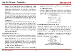
• Over Ride
menu allows entering one of the 16 different alarms
that will trip this relay regardless of the Votes entries. There
are four alarms per channel and four channels and any one of
these alarms may be used as the Over Ride. This feature is
useful when one channel’s alarm has more significance than
the others.
• Horn
controls how activating this relay will affect the horn driver
circuit connected to J2 on the motherboard. Choices are NO,
STEADY or PULSE. Warning level alarms might be set to
pulse the horn and high alarms set for steady. Personnel can
then know which alarm level is present by hearing the pulsing
or steady horn.
• Turning Acknowledge ON (not allowed on Relay 1) allows Relay
2 to be deactivated during alarm conditions by an Alarm Reset.
This is useful if another audible device is being driven by the
relay. The acknowledge feature is not available for Relay 1 since
it is often used for driving a warning light and Relay 2 for driving
a horn. It could be dangerous if an operator acknowledged
the horn AND the light since no indication of the high alarm
condition would remain.
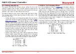
2.3.2 Clock / Delays Menu
The HA40 monitors signals from inputs that may require varying times
to stabilize after power is applied and after calibrations are complete.
• Alarm Refresh
menu allows reactivation of Acknowledged
alarms after the time period expires. This feature is used
primarily to restart audible alarm devices after having been
silenced by an acknowledge function (via serial port or pressing
the Alarm Reset button). An entry of 0 seconds effectively
disables the Alarm Refresh function.
• Warm-Up Delay
menu allows setting how long alarm relays
remain disabled after power is applied.
• Cal Delay
determines how long alarm relays are inhibited after
completing a calibration.
• Time
and
Date
menu items are for setting the correct time and
date. The HA40 is equipped with a 24-hour clock and calendar.
Time of day must be entered in 24 hour mode. For example,
6:00:00 PM = is indicated as18:00:00.
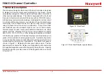
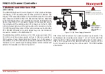
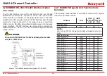
Figure 2-9. Clock/Delays Menu
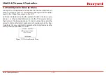
2.3.3 COMM Port Remote ID Menu
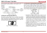
The system Remote ID menu allows setting RTU address for the
optional slave Modbus serial port (requires 10-0253 Modbus option
PCB – see Section 3.2). This slave port may be used to transfer HA40
data to a host device such as a PC, PLC, DCS or even other Honeywell
Analytics controllers, such as the 16 Channel HA71. The slave port
is addressable, allowing many HA40 controllers to be connected to a
single RS-485 cable. A converter is available to make this port also
compatible with Ethernet TCP/IP networks.
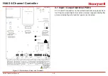
Figure 2-10. COMM Port ID Remote Menu
Содержание HA40
Страница 6: ...HA40 4 Channel Controller HA40 Technical Manual 1 1 1 General Description ...
Страница 11: ...HA40 4 Channel Controller HA40 Technical Manual 2 1 2 Operation ...
Страница 21: ...HA40 4 Channel Controller HA40 Technical Manual 2 11 ...
Страница 22: ...HA40 4 Channel Controller HA40 Technical Manual 3 1 3 Motherboard Interface PCB ...
Страница 31: ...HA40 4 Channel Controller HA40 Technical Manual 4 1 4 Enclosures ...
Страница 34: ...HA40 4 Channel Controller HA40 Technical Manual 5 1 5 Parts List ...
Страница 36: ...HA40 4 Channel Controller HA40 Technical Manual 6 1 6 Specifications ...
Страница 38: ...HA40 4 Channel Controller HA40 Technical Manual 7 1 7 Warranty ...


