HA40 4-Channel Controller
HA40 Technical Manual
2-4
2.2.3 Fault / Alarm 1 / Alarm 2 / Alarm 3 Set-Up
Menus
Alarm 1
,
2
and
3
have identical menus. The only difference between
each is that A1 front panel LED indicators are yellow while A2 and A3
are red. Typical applications often have A1 set at a WARN level, A2
at a HIGH level and A3 at a higher SHUT DOWN level. However, it is
important to understand there is no functional difference between A1,
A2 and A3 (since their configuration menus are identical, only one is
shown in Figure 2-19). The
Fault
menu is identical to A1, A2, A3 except
Fault alarms are always low trips (alarm activates as input goes below
the set point) and Fault alarms may not be set for latching operation.
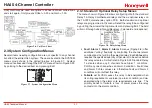
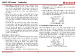
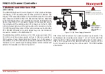
Figure 2-3. Alarm/Fault Setup Menu
• Set Point
is entered in engineering units and determines
the value at which the alarm trips. For example, if a channel
monitors 0-50 ppm H
2
S and the desired alarm level is 10 ppm,
the correct entry is 10.00. A one percent dead band prevents
alarm chatter. This means after tripping an alarm the input must
move at least 1% of full scale back through the setpoint for the
alarm to auto reset.
• The
ON Delay
/
OFF Delay
entries allow ON and OFF time
delays affecting how long the trip-point must be surpassed
before an alarm event transition occurs. ON delays are limited
to 10 seconds while OFF delays may be as long as 120 minutes.
Delays are useful in many applications to prevent nuisance
alarms and unwanted cycling into and out of alarm conditions.
• Low Trip
is set for NO to increase alarms or YES to decrease
alarms to determine if the alarm activates upon exceeding or
falling below the set-point.
• Latching
determines either manual or automatic alarm reset
operation. YES requires a manual Alarm Reset to unlatch the
alarm even though an alarm condition no longer exists. YES
also causes this alarm’s common relay, front panel LED, and
optional discrete relay to latch. NO allows all outputs for this
alarm to automatically reset after the alarm condition clears.
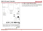
Common alarm LED indicators on the left side of the front panel
indicate the status of A1, A2 A3 alarms. The common Fault LED is on
the lower right side of the front panel. Any new alarm event causes
the associated LED to flash until an Alarm Reset occurs causing
an acknowledged steady on condition. Operators should recognize
new alarms by a flashing LED. Alarm Reset also acknowledges, or
deactivates, audible devices driven by the AUDIBLE ALARM option
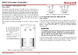
connector J2 (see
Figure 3.2
)
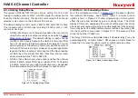
2.2.4 Configure Menu To Define Channel
The next menu option, after the Alarm menu, is Configure. It
allows setting Name and EUNIT 10 digit ASCII fields, defines the
measurement range with ZERO & SPAN entries, number of Decimal
Points of resolution the reading will have, and if the channel is Active.
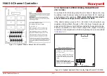
Figure 2-4. Configure Menu to Define Channel
Содержание HA40
Страница 6: ...HA40 4 Channel Controller HA40 Technical Manual 1 1 1 General Description ...
Страница 11: ...HA40 4 Channel Controller HA40 Technical Manual 2 1 2 Operation ...
Страница 21: ...HA40 4 Channel Controller HA40 Technical Manual 2 11 ...
Страница 22: ...HA40 4 Channel Controller HA40 Technical Manual 3 1 3 Motherboard Interface PCB ...
Страница 31: ...HA40 4 Channel Controller HA40 Technical Manual 4 1 4 Enclosures ...
Страница 34: ...HA40 4 Channel Controller HA40 Technical Manual 5 1 5 Parts List ...
Страница 36: ...HA40 4 Channel Controller HA40 Technical Manual 6 1 6 Specifications ...
Страница 38: ...HA40 4 Channel Controller HA40 Technical Manual 7 1 7 Warranty ...


