background image

HA40 4-Channel Controller

Technical Manual

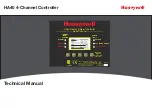
ALARM 1

ALARM 2

ALARM 3

COMMON

LEVEL

ALARMS

KEYPAD

CAL IN PROGRESS

FAULT ALARM

Magnetic

Keypad

(Keypad buttons

behind door)

HA40 Display & Alarm Controller

STATUS

LED's

Quad Channel

Edit

Alarm

Reset

Next

219995

Classified to CSA C22.2 NO. 152 for combustibles

detection. Class I, DIV.2, Groups A,B,C,D

READ & UNDERSTAND MANUAL!

S/N 90-

or 10-30 VDC @ 3 WATTS

Power = 100-240 V~, 50/60 Hz, .45 A

Содержание HA40

Страница 1: ...S FAULT ALARM Magnetic Keypad Keypad buttons behind door HA40 Display Alarm Controller STATUS LED s Quad Channel Edit Alarm Reset Next 219995 Classified to CSA C22 2 NO 152 for combustibles detection Class I DIV 2 Groups A B C D READ UNDERSTAND MANUAL S N 90 or 10 30 VDC 3 WATTS Power 100 240 V 50 60 Hz 45 A ...

Страница 2: ...tions of this instrument have been assessed by CSA for 122 2 No 152 performance requirements for mA input only This equipment is suitable for use in Class I Division 2 Groups A B C and D or non hazardous locations only EXPLOSION HAZARD SUBSTITUTION OF COMPONENTS MAY IMPAIR SUITABILITY FOR CLASS I DIVISION 2 EXPLOSION HAZARD DO NOT REPLACE FUSE UNLESS POWER HAS BEEN SWITCHED OFF OR THE AREA IS KNOW...

Страница 3: ...3 1 3 1 Power Supply Requirements 1 3 Warning 1 4 1 3 2 Relays 1 4 1 3 3 Ambient Temperature Range 1 4 1 3 4 Humidity Range 1 4 1 3 5 Altitude 1 4 1 3 6 Housings Installation Categories 1 5 1 3 7 Approvals 1 5 1 3 3 Ambient Temperature Range 1 5 1 3 4 Humidity Range 1 5 1 3 5 Altitude 1 5 1 3 6 Housings Installation Categories 1 5 1 3 7 Approvals 1 5 2 Operation 2 Operation 2 2 2 1 Setup Menu Conf...

Страница 4: ...iguration Menus 2 7 2 3 1 Standard Optional Relay Setup Menus 2 7 2 3 2 Clock Delays Menu 2 8 2 3 3 COMM Port Remote ID Menu 2 8 2 3 4 Analog Setup Menu 2 9 2 3 5 Horn Acknowledge Menu 2 9 2 4 HA40 System Security Menu 2 10 3 Motherboard Interface PCB 3 Motherboard Interface PCB 3 2 3 1 Input Output Optional PCB s 3 3 3 1 2 Optional Analog Input PCB 3 4 3 1 3 Optional Discrete Relay PCB s 3 4 3 1 ...

Страница 5: ...0 Technical Manual iv 4 2 HA40PY Polycarbonate 4 2 4 3 HA40XP NEMA 7 Explosion Proof Wall Mount Enclosure 4 3 5 Parts List 5 Parts List 5 2 6 Specifications 5 Specifications 6 2 7 Warranty Honeywell Analytics Warranty Statement 7 2 ...

Страница 6: ...HA40 4 Channel Controller HA40 Technical Manual 1 1 1 General Description ...

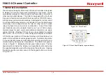
Страница 7: ...e trends and engineering units System configuration is via user friendly menus and all configuration data is retained in non volatile memory during power interruptions The HA40 front panel is shown in Figure 1 1 displaying the bar graph data screen The five keypad symbols below the display are magnetically activated using the supplied magnetic wand without opening the enclosure Opening the enclosu...

Страница 8: ... 1 4 Live readings and their Eunits tag are displayed across the top of each trend screen Channel numbers are shown in the upper right and are selected by the Next key A1 A2 and A3 alarm levels appear as horizontal dashed lines across the screen 1 3 Specifications 1 3 1 Power Supply Requirements The HA40 is equipped with an integral 15 watt or 50 watt depending on the configuration universal AC in...

Страница 9: ...tion 5 Specifications WARNING A backup or external DC power source DOES NOT source auxiliary power output see figure 3 1 TB3 1 3 2 Relays Two mechanical dry contact Common Form C relays are standard and may be mapped to various alarm events as described in Section 2 3 1 HA40 s may also be equipped with optional solid state common Form A relays see Section 5 Specifications for details in applicatio...

Страница 10: ...e 219995 1 3 3 Ambient Temperature Range 25 to 50 degrees C 1 3 4 Humidity Range 0 to 90 R H Non Condensing 1 3 5 Altitude Recommended up to 2000 meters 1 3 6 Housings Installation Categories NEMA 4X wall mount DIV 2 Groups A B C D Category II and pollution degree 3 NEMA 4X IP66 NEMA 4 painted carbon steel SS316 NEMA4X Polycarbonate NEMA4X NEMA 7 wall mount for DIV 1 2 Groups B C D includes O ring...

Страница 11: ...HA40 4 Channel Controller HA40 Technical Manual 2 1 2 Operation ...

Страница 12: ...e steady after Acknowledged by pressing the Alarm Reset key A SECURITY menu offers a password feature to prevent tampering with HA40 parameters A sign on screen appears briefly after power is applied that indicates what type of input output options are configured with the unit 2 1 Setup Menu Configuration Variables inside the CHANNEL see Section 2 2 and SYSTEM see Section 2 3 menu trees allow HA40...

Страница 13: ...ds the field into non volatile memory where it is retained indefinitely Without a cursor present the Next key closes open menus in reverse order and returns the LCD to the data display 2 2 1 Setup Configuration Menus The SETUP menu shown in the middle of Figure 2 16 and in Figure 2 17 is accessed by pressing Edit when any data display is present This is the entry level screen to all Channel System...

Страница 14: ...d to 10 seconds while OFF delays may be as long as 120 minutes Delays are useful in many applications to prevent nuisance alarms and unwanted cycling into and out of alarm conditions Low Trip is set for NO to increase alarms or YES to decrease alarms to determine if the alarm activates upon exceeding or falling below the set point Latching determines either manual or automatic alarm reset operatio...

Страница 15: ...the Min Max Raw Counts menus described in section 2 7 4 Decimal Point Resolution Resolution of the displayed channel value is configured in the Decimal Pts menu by setting the number of digits trailing the decimal point Displayed readings are limited to a maximum of four digits with a polarity sign Auto ranging displays the highest resolution allowed by this menu s decimal point entry For example ...

Страница 16: ...ODE automatically exits if no keystroke is detected after 5 minutes Use the following step by step procedure to perform ZERO and SPAN calibrations 1 To enter the CAL SETUP from any data display press the dual purpose down arrow CAL key then use the up down arrow keys to select the channel to calibrate 2 Stimulate the monitor to be calibrated with an appropriate ZERO calibration standard Observe th...

Страница 17: ...on PCB Both standard and optional relays are programmed in this menu Select the relay to be configured by pointing the arrow at the top menu item and pressing Edit The field will scroll through all eight possible relays 2 standard and 6 optional Figure 2 8 Relay Setup Menu Fault Alarm 1 Alarm 2 Alarm 3 menus Figure 2 8 offer additional voting flexibility by controlling the channel alarm combinatio...

Страница 18: ...require varying times to stabilize after power is applied and after calibrations are complete Alarm Refresh menu allows reactivation of Acknowledged alarms after the time period expires This feature is used primarily to restart audible alarm devices after having been silenced by an acknowledge function via serial port or pressing the Alarm Reset button An entry of 0 seconds effectively disables th...

Страница 19: ...ng at 18mA input the correct A D Min Max Raw counts menu entries would become 1200 to 3600 00 D A Min Max Raw counts menu options define the optional future 4 20mA output PCB s input Ideally 200 to 1000 yields a 4 20mA output but very slight modifications may be needed to provide precise 4mA and 20mA values for each channel Figure 2 11 Analog Setup Menu 2 3 5 Horn Acknowledge Menu J2 on the mother...

Страница 20: ...ocked message on the LCD Authorized individuals locking the system should first enter a name phone or other contact information into the 12 character field on the top line of the Security screen To lock or unlock the system the correct 4 digit authorization number must be entered into the Pass Code field It is very important to remember the 4 digit code since the factory must be consulted if it is...

Страница 21: ...HA40 4 Channel Controller HA40 Technical Manual 2 11 ...

Страница 22: ...HA40 4 Channel Controller HA40 Technical Manual 3 1 3 Motherboard Interface PCB ...

Страница 23: ...t TB3 Auxiliary Power Output terminals Figure 3 1 If AC power is unavailable or if a DC battery back up supply is needed TB1 provides terminals for DC power input Blocking diodes isolate internal and external DC supplies as shown in Figure 3 1 2 Amp 250V 5x20mm fuse located under terminal cover WARNING For continued protection against fire replace only with same type and rating of fuse Universal I...

Страница 24: ...ut for remote devices such as transmitters lights relays etc 350mA MAX see Figure 3 0 TB4 5 amp resistive SPDT form C dry contact relay outputs Use appropriate diode snubber devices when switching inductive loads TB5 Universal 100 240VAC primary power source terminals Important GND terminal 3 must be tied to earth for correct shielding of incoming signals TB2 Dry contact input for use with optiona...

Страница 25: ...ohm 4 20mA terminator Spare Spare 100 ohm 4 20mA terminator These 5 resistors are socketed for easy replacement Terminators are connected between each channel s HI LO terminals LO 24VDC Power Supply Common 24VDC 24VDC Power Supply output Figure 3 3 Optional Analog Input PCB P N 10 0221 Figure 3 4 Wiring for 2 and 3 wire Transmitters 3 1 3 Optional Discrete Relay PCB s P N 10 0222 The optional Disc...

Страница 26: ...e capable of driving 20mA through a 750 ohm load Outputs are self powered and DC power should not be provided by the receiving device Precision calibration of the 4 20mA output DAC digital to analog converter is accomplished via the Analog Setup menu as described in Section 2 3 4 1 2 3 4 4 20mA OUTPUTS CH1 CH2 TB1 TB1 Assy 10 0308 4 20mA Outputs are sourcing and 24 VDC power must not be supplied b...

Страница 27: ...stallation guidelines when using the 10 0253 option Figure 3 7 HA40 Modbus Interface Option P N 10 0253 3 2 1 MODBUS Register And Function Code Summary The following table identifies the available modbus RTU register locations and function codes VARIABLE ALIAS READ FUNCTION CODE WRITE FUNCTION CODE Read Write Coils Alarm Ack Reset 2001 1 5 NOTE After writing a TRUE to this register the HA40 automa...

Страница 28: ... value representing the D2A value of 800 0 to 4000 100 after all cal features are applied Chan 1 Status 31005 4 NA Chan 2 Status 31006 4 NA Chan 3 Status 31007 4 NA Chan 4 Status 31008 4 NA 16 bit status word bit assignment for each channel ALARM1_BELOW_BIT ALARM2_BELOW_BIT ALARM3_BELOW_BIT ALARM1_LATCH_BIT ALARM2_LATCH_BIT ALARM3_LATCH_BIT ALARM3_ACTIVE_BIT CHANNEL_DISABLED_BIT CHANNEL_CAL_BIT BI...

Страница 29: ...13 BIT14 BIT15 Relay Status 31012 4 NA Bit set to 1 LED Blinking bit set to 0 LED is steady ON STANDARD RELAY 1 STANDARD RELAY 2 OPTION RELAY 1 OPTION RELAY 2 OPTION RELAY 3 OPTION RELAY 4 OPTION RELAY 5 OPTION RELAY 6 INPUT FAULT RELAY Reserved Reserved Reserved Reserved Reserved Reserved Reserved BIT0 BIT1 BIT2 BIT3 BIT4 BIT5 BIT6 BIT7 BIT8 BIT9 BIT10 BIT11 BIT12 BIT13 BIT14 BIT15 VARIABLE ALIAS...

Страница 30: ...32 3 NA Chan 4 Span Real 41033 3 NA Chan 4 Span Divisor 41034 3 NA Chan 4 Alarm 1 Real 41035 3 NA Chan 4 Alarm 1 Divisor 41036 3 NA Chan 4 Alarm 2 Real 41037 3 NA Chan 4 Alarm 2 Divisor 41038 3 NA Chan 4 Alarm 3 Real 41039 3 NA Chan 4 Alarm 3 Divisor 41040 3 NA Memory ASCII Strings User Info Chan 1 40401 40405 3 NA User Info Chan 2 40406 40410 3 NA User Info Chan 3 40411 40415 3 NA User Info Chan ...

Страница 31: ...HA40 4 Channel Controller HA40 Technical Manual 4 1 4 Enclosures ...

Страница 32: ...0 4 12 5 84 7 56 2 70 6 20 11 81 12 90 13 65 C L 2 56 8 84 9 84 1 2 in NPTConduit Fittings Typical 4 places Single 1 4 Turn Latch Instrument Viewing Window Notes Part 1000 2377 316 Stainless Steel Part 1000 2378 Painted Carbon Steel Side View Front View Bottom View Material Figure 4 1 NEMA Painted Carbon Steel or Stainless Steel Enclosure 4 2 HA40PY NEMA 4X Polycarbonate Enclosure CAUTION Nonmetal...

Страница 33: ...l 4 3 4 3 HA40XP NEMA 7 Explosion Proof Wall Mount Enclosure The HA40XP enclosure shown in Figure 4 3 is an aluminum NEMA 7 wall mount enclosure designed for use in potentially hazardous areas Figure 4 3 NEMA 7 Explosion Proof Wall Mount Enclosure ...

Страница 34: ...HA40 4 Channel Controller HA40 Technical Manual 5 1 5 Parts List ...

Страница 35: ...HA40 4 Channel in NEMA 7 Enclosure incl Magnetic Keypad for nonintrusive control 4 20mA I O Options 10 0221 4 Quad 4 20mA Analog Input PCB Options and Accessories 10 0222 Relay Option to add six 5 amp Form C relays 10 0227 Modbus RS 232 RS 485 Option 10 0284 Division 2 red xenon strobe light includes mounting to top of NEMA 4 models 1000 1892 100db piezo audible NEMA 4X enc only ...

Страница 36: ...HA40 4 Channel Controller HA40 Technical Manual 6 1 6 Specifications ...

Страница 37: ...to 122ºF Operating humidity range 0 to 90 RH non condensing Operating altitude 2000m 6562 ft Audible alarm 100 dB Display 128 x 64 backlight graphic LCD Visual Indicators 6 LED status indicators Pollution degree N4 3 Enclosure N4 NEMA 4X Div 2 Groups A B C D Category II Enclosure XP NEMA 7 Div 1 2 Groups B C D Dimensions H x W x D N4 10 32 x 8 92 x 3 17 23 62 x 22 66 x 8 05cm XP 15 10 x 13 x 6 25 ...

Страница 38: ...HA40 4 Channel Controller HA40 Technical Manual 7 1 7 Warranty ...

Страница 39: ...se warranty terms Time and travel expenses for on site warranty services will be charged at Honeywell Analytics normal billing rates Contact your Honeywell Analytics representative for information on available Service Contracts Honeywell Analytics shall not be liable for any loss or damage whatsoever or howsoever occasioned which may be a direct or indirect result of the use or operation of the Co...

Страница 40: ...etection honeywell com Europe Middle Easst and Africa ha global service honeywell com www honeywell com Asia Pacific Honeywell Analytics 508 Kolon Science Valley l 187 10 Guro Dong Guro Gu Seoul 152 050 Korea Tel 82 2 2025 0300 Fax 82 2 2025 029 anapitics ap honeywell com Please Note While every effort has been made to ensure accuracy in this publication no responsibility can be accepted for error...

Отзывы: