background image


________________________________________________________________________________________________________ 
56 
 

Connecting a Second Monitor 


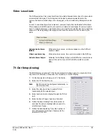
All DVRs offer both VGA and DVI-D video outputs that can be used simultaneously. Live 
video will always appear on one output while a second can be used to display search or 
setup screens. 


1.


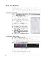
Click Exit on the Live View screen and select Restart in Windows Mode. 


2.


Right-click the Desktop and select Properties. 


3.


Click the Settings tab. 


4.


Click the secondary display and click the Extend my Windows desktop onto this 
monitor check box. 


Tip 

Refer to the display documentation for the proper resolution settings.


5.


Click OK and confirm the change. 


6.


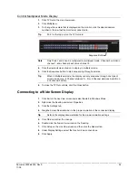
Double-click the Fusion Server icon on the Desktop. 


7.


Click Setup on the Live View screen and then click the General tab. 


8.


Under Function, select the Dual Monitor check box. 


9.


Click Apply. 


Содержание Fusion IV

Страница 1: ...________________________________________________________________________________________________________ Document 800 05305 Rev A 11 09 FUSION IV DVR Digital Recording and Transmission System User Guide ...

Страница 2: ...Warnings and Safeguards ________________________________________________________________________________________________________ 2 Revisions Issue Date Revisions A 11 09 Initial Release ...

Страница 3: ...no guarantee that interference will not occur in a particular installation If this equipment does cause harmful interference to radio or television reception which can be determined by turning the equipment off and on the user is encouraged to try to correct the interference by one or more of the following measures Reorient or relocate the receiving antenna Increase the separation between the equi...

Страница 4: ...H PLUG NOT ESTABLISHING EARTHING CONTINUITY WHEN INSERTED INTO DANISH SOCKET OUTLETS VIGTIGT LEDEREN MED GRØN GUL ISOLATION MÅ KUN TILSLUTTES EN KLEMME MÆRKET IEC 417 NO 5019 ELLER IEC 417 NO 5017 FOR TILSLUTNING AF DE ØVRIGE LEDERE SE MEDFØLGENDE INSTALLATIONSVEJLEDNING SUPPLY CORD OF SINGLE PHASE EQUIPMENT HAVING A RATED CURRENT NOT EXCEEDING 13 A SHALL BE PROVIDED WITH A PLUG ACCORDING TO THE H...

Страница 5: ...OWING DIMENSION SHEETS SEV 6532 2 1991 PLUG TYPE 15 3P N PE 250 400 V 10 A SEV 6533 2 1991 PLUG TYPE 11 L N 250 V 10 A SEV 6534 2 1991 PLUG TYPE 12 L N PE 250 V 10 A IN GENERAL EN 60309 APPLIES FOR PLUGS FOR CURRENTS EXCEEDING 10 A HOWEVER A 16 A PLUG AND SOCKETOUTLET SYSTEM IS BEING INTRODUCED IN SWITZERLAND THE PLUGS OF WHICH ARE ACCORDING TO THE FOLLOWING DIMENSION SHEETS PUBLISHED IN FEBRUARY ...

Страница 6: ...d when addressing this concern E Reliable Earthing Reliable earthing of rack mounted equipment should be maintained Particular attention should be given to supply connections other than direct connections to the branch circuit e g use of power strips UL Notice Underwriters Laboratories Inc has not tested the performance or reliability of the security or signaling aspects of this product UL has onl...

Страница 7: ...s Reorient or relocate the receiving antenna Increase the separation between the equipment and the receiver Connect the equipment into an outlet on a circuit different from that which the receiver is connected Consult the dealer or an experienced radio TV technician for help The mass storage system does not product hazardous laser radiation Because laser light emitted inside the mass storage syste...

Страница 8: ...7 Power Cord Protection Power supply cords should not be routed so that they are not likely to be walked on or pinched by items placed against them paying particular attention to cords at plugs convenience receptacles and the point where they exit from the product 8 Overloading Do not overload wall outlets extension cords or integral convenience receptacles as this can result in a risk of fire or ...

Страница 9: ...s Refer all servicing to qualified personnel 17 Replacement Parts When replacement parts are required be sure the service technician has used replacement parts specified by the manufacturer or have the same characteristics as the original part Unauthorized substitutions may result in fire electric shock or other hazards 18 Safety Check Upon completion of any service or repairs to this unit ask the...

Страница 10: ...isture condensation damages the DVR Read the following information carefully Moisture condensation can occur in the following cases When this product is brought directly from a cool location to a warm location When this product is moved to a hot and humid location from a cool location When this product is moved to a cool and humid location from a warm location When this product is used in a room w...

Страница 11: ...ECTRICAL SHOCK DO NOT EXPOSE THIS APPLIANCE TO RAIN OR MOISTURE DANGEROUS HIGH VOLTAGES ARE PRESENT INSIDE THE ENCLOSURE DO NOT OPEN THE CABINET REFER SERVICING TO QUALIFIED PERSONNEL ONLY CAUTION CAUTION TO REDUCE THE RISK OF ELECTRIC SHOCK DO NOT REMOVE COVER OR BACK NO USER SERVICEABLE PARTS INSIDE REFER SERVICING TO QUALIFIED SERVICE PERSONNEL C A U T I O N RISK OF ELECTRIC SHOCK DO NOT OPEN ...

Страница 12: ...Warnings and Safeguards ________________________________________________________________________________________________________ 12 ...

Страница 13: ...6 Channel 24 PCI Card Configurations 25 120 IPS 16 Channel 25 240 IPS 8 16 Channel 25 240 IPS 32 Channel 25 480 IPS 16 Channel 26 480 IPS 32 Channel 26 H 264 240 IPS 8 Channel 27 H 264 480 IPS 16 Channel 27 5 Getting Started 28 Identifying Included Components 28 Keyboard Setup 29 Mouse Setup 29 Monitor Setup 30 Power Setup 30 Connecting a Video Source to the DVR 31 Looping Outputs 32 Looping Outpu...

Страница 14: ... Camera Finder 46 Assigning a Network Device to a Channel 46 Assigning Audio Channels to a Network Device 47 Camera Configuration 48 Displaying More Columns 48 Accessing the Device Configuration Menu 48 Motion 49 Regular Interval Recording 49 Enable Sabotage Detection 49 Creating a Motion Area 50 Removing a Motion Area 50 General Setup 51 Voice Warning 52 Intensive Recording Overview 52 Enabling I...

Страница 15: ...nagement 76 Setup Log Management Options 76 User Management 77 Add a New User 77 User Rank 78 Changing the Administrator Password 78 Default Administrator Password 78 Status Check Email 79 General 79 Users 79 Storage Check 80 Recording Data Check 80 SMART Information 80 SMART Alert 81 Alarm Event 81 Data Management 81 Information 82 PTZ 82 Instant Recording 83 Activate Instant Recording 83 Searchi...

Страница 16: ...98 Performing a Preview Search 99 Object Search 100 Performing an Object Search 100 Status Search 101 Performing a Status Search 101 Motion Search 102 Performing a Motion Search 102 Audio 102 9 Pan Tilt Zoom 103 Pan Tilt Zoom Overview 103 Setting up a PTZ Camera 103 Supported Protocols 104 Advanced PTZ Setup 105 Creating and Viewing Preset Positions 106 Creating a Preset 106 Viewing a Preset 106 U...

Страница 17: ...8 12 LDAP Integration 119 Features 119 Installing LDAP 120 13 Honeywell Video Analytics Integration 123 Overview 123 Important Notes 123 Log In to Honeywell Video Analytics Configuration 124 Add the Fusion Server Login to Honeywell Video Analytics 124 Set up Honeywell Video Analytics Communication 125 Honeywell Video Analytics Modules 126 Launch Honeywell Video Analytics Modules 126 Video Analytic...

Страница 18: ... Remote Client Minimum Requirements Error Bookmark not defined Remote Client Recommended Requirements Error Bookmark not defined Installing the Fusion Remote Software 141 Setting up the Server to Accept Incoming Communications 142 Setting up the Fusion Remote Software 143 Creating a New Remote Connection 143 FVMS Overview 144 Configuring the Server for Remote Connection 144 Connecting to a DVR 144...

Страница 19: ...rver software offers unparalleled stability security and ease of use Accordingly a security investment has never been easier to maintain Multiple users may simultaneously connect through any network connection for instantaneous live viewing digital search and off site video storage Users can also connect remotely through DSL Cable Modems ISDN or 56K dial up This powerful software enables users to ...

Страница 20: ... on model and optional accessory component Pan Tilt Zoom Controls Simultaneous Video Search Playback and Backup Video Indexes for Easy Searching Multiple Levels of Security Access Up to 32 Looping Outputs dependant on model Optional POS ATM and Video Analytics Support Analog Spot Monitor Output Up to 32 Camera Inputs dependant on model High Performance Durable Rack mount Case NTSC and PAL supporte...

Страница 21: ...finition Digital Recorders are housed in a high performance and versatile 4U Aluminum Rack Mount case allowing easy storage of multiple DVRs for enterprise applications Every Fusion DVR Unit comes equipped with the latest technology Intel Dual Core Processor minimum 100 1000 Network Interface Card NIC 1 GB of System Memory minimum 8x USB 2 0 Ports DVD RW Recorder Full Duplex High Fi Sound Function...

Страница 22: ... Controls and LEDS The front panel of the DVR unit contains the devices that will be commonly used for data removal retrieval and backup replacement The most common components and buttons are shown below DVD RW Drive Hard Drive Activity LED USB Ports Hard Drive Trays Fan Activity LED Hard Drive Power Buttons Power Switch Cooling Fan Air Intake ...

Страница 23: ... CH 14 in CH 15 in CH 16 in 1 2 3 4 5 6 7 8 9 10 11 12 13 14 15 16 CONTROL 1 2 3 4 5 6 7 8 9 10 11 12 13 14 15 1 6 COM SENSOR ON OFF ON OFF BNC A BNC B DVI D 1394 CH 17 in CH 18 in CH 19 in CH 20 in CH 21 in CH 22 in CH 23 in CH 24 in CH 25 in CH 26 in CH 27 in CH 28 in CH 29 in CH 30 in CH 31 in CH 32 in AC Power Connector Secondary Power Switch PS 2 Mouse Input PS 2 Keyboard Input DVI D Port SVG...

Страница 24: ...ROL 1 2 3 4 5 6 7 8 9 10 11 12 13 14 15 1 6 COM SENSOR ON OFF ON OFF DVI D 1394 CH 1 Out CH 2 Out CH 3 Out CH 4 Out CH 5 Out CH 6 Out CH 7 Out CH 8 Out CH 9 Out CH 10 Out CH 11 Out CH 12 Out CH 13 Out CH 14 Out CH 15 Out CH 16 Out Looping Termination Switch BNC Connectors for Video Input Looping Output Control Alarm Outputs Sensor Inputs AC Power Connector Secondary Power Switch PS 2 Mouse Input P...

Страница 25: ...______________ Document 800 05305 Rev A 25 11 09 PCI Card Configurations 120 IPS 16 Channel 240 IPS 8 16 Channel 240 IPS 32 Channel RCA Video Out Audio Inputs RS 485 Interface DB 9 Serial Input RCA Video Out Audio Inputs RS 485 Interface DB 9 Serial Input RCA Video Out Audio Inputs RS 485 Interface DB 9 Serial Input ...

Страница 26: ..._____________________________________________ 26 480 IPS 16 Channel 480 IPS 32 Channel RCA Video Out Audio Inputs RS 485 Interface SVGA Monitor Output DVI Output DB 9 Serial Input RCA Video Out SVGA Monitor Output Audio Input Cable Adapter RS 485 Interface DVI Output DB 9 Serial Input ...

Страница 27: ..._________________________________________________ Document 800 05305 Rev A 27 11 09 H 264 240 IPS 8 Channel H 264 480 IPS 16 Channel Audio Input Cable Adapter RCA Video Out RS 485 Interface DB 9 Serial Input Audio Input Cable Adapter RCA Video Out RS 485 Interface DB 9 Serial Input ...

Страница 28: ...e missing contact the dealer to arrange for a replacement Mouse Keyboard DVR Key PTZ Adapter DVR Repair Software Disc Power Cord User Guide Mouse Pad 8 CH Audio Input Cable 16 CH Audio Input Cable 16 CH Video Looping Output Cable RCA Video Adapter 8 CH Audio Input cable included with the H 264 models x2 with the 16 CH model 16 CH Audio Input cable included standard with the 16CH 480 400 IPS models...

Страница 29: ...ht button Quickly pressing and releasing one of these buttons is called clicking Sometimes it will be necessary to double click or click the same button twice quickly In this manual Click means to position the mouse cursor over an item and to single click the left button Right click means to position the mouse cursor over an item and to single click the right button Double click means to position ...

Страница 30: ...t least 32 Bit Power Setup Attach the AC power cable to the rear of the DVR WARNING To reduce the risk of electrical shock or damage to the equipment Do not disable the power grounding plug The grounding plug is an important safety feature If the electrical plug you are using does not have a ground plug receptacle contact a licensed electrician to have it replaced with a grounded electrical outlet...

Страница 31: ...in CH 11 in CH 12 in CH 13 in CH 14 in CH 15 in CH 16 in CH 1 Out CH 2 Out CH 3 Out CH 4 Out CH 5 Out CH 6 Out CH 7 Out CH 8 Out CH 9 Out CH 10 Out CH 11 Out CH 12 Out CH 13 Out CH 14 Out CH 15 Out CH 16 Out CH 1 in CH 2 in CH 3 in CH 4 in CH 5 in CH 6 in CH 7 in CH 8 in CH 9 in CH 10 in CH 11 in CH 12 in CH 13 in CH 14 in CH 15 in CH 16 in CH 1 Out CH 2 Out CH 3 Out CH 4 Out CH 5 Out CH 6 Out CH ...

Страница 32: ...annel DVRs may have up to 32 looping outputs Connect the included 16 channel video cables to the BNC Expansion Ports CH 1 in CH 2 in CH 3 in CH 4 in CH 5 in CH 6 in CH 7 in CH 8 in CH 9 in CH 10 in CH 11 in CH 12 in CH 13 in CH 14 in CH 15 in CH 16 in CH 1 Out CH 2 Out CH 3 Out CH 4 Out CH 5 Out CH 6 Out CH 7 Out CH 8 Out CH 9 Out CH 10 Out CH 11 Out CH 12 Out CH 13 Out CH 14 Out CH 15 Out CH 16 O...

Страница 33: ...ach DVR may have up to 16 Sensor inputs These inputs can be used with devices such as infrared sensors motion devices glass break alarms door and window trips and many more The Sensor inputs can be set to Normally Open or Normally Closed within the Fusion Server software There are 4 Commons and 16 inputs There is no power supplied to the ports so an external power supply must be used if power beco...

Страница 34: ...current devices use an external relay Maximum voltage is 24V AC 1 amp Output uses a Form C Relay NC C NC Connecting a 16 Channel Audio Input Cable The 16 channel audio input cable standard with the 16Ch 480 400 IPS Fusion DVR connects to a single serial port in the back of the unit When connecting the 16 Channel Audio Input Cable make sure to properly secure the cable to insure there is no loss of...

Страница 35: ...es with the number assigned to the camera This is normally done utilizing a dip switch configuration method on the addressable dome Tip Honeywell recommends that the ID of the camera coincide to the input number on the DVR This will make future troubleshooting and configuration less complex Attaching the 4 Pin Adapter 240 480 H 264 models 1 Locate the PTZ adapter cable 2 Connect the wires of the P...

Страница 36: ... more information USB External Hard Drive USB Modem Fiber Network Interface Adapter 4 Port Analog Output Card Gigabit 10 100 1000 NIC Adapter 16 Port Audio Card Fusion Remote Video Software External 1U Chassis SATA Storage up to 8 Terabyte External 3U Chassis SATA Storage up to 32 TB HVR NVR Upgrade 4CH Multiplexed Analog Output card Internal Raid 5 Honeywell Video Analytics Software IDM Integrate...

Страница 37: ...displayed as the various hardware and software subsystems are activated Under normal circumstances the user should not be asked to respond to these messages If asked to respond to the messages adding a Printer Monitor etc for the first time follow the instructions carefully Turning Off the DVR 1 Select the Exit button from the main screen 2 Select Yes The DVR will shut itself off automatically onc...

Страница 38: ...rogram defaults to the Live View screen The following diagram outlines the buttons and features used on the Live View screen Become familiar with these options as this is the screen that will be displayed the majority of the time Camera Display Buttons Current Date Time Displays Connected Users Status of Activates Control Outputs Status of Activates Alarm Sensors Menu Buttons ...

Страница 39: ... camera is not being recorded Special Recording There are several different types of DVR Special Recording situations Text is displayed on the camera indicating either sensor or instant when activated Sensor Displays when a sensor associated with a given camera is activated Instant Instant Recording is a manual recording activation for the selected camera Regardless of the recording method Instant...

Страница 40: ...meras 5 8 in the Video Display Area 3rd Four Cameras Displays cameras 9 12 in the Video Display Area 4th Four Cameras Displays cameras 13 16 in the Video Display Area 1st Nine Cameras Displays cameras 1 9 in the Video Display Area 2nd Nine Cameras Displays cameras 10 18 in the Video Display Area Camera Multi View 1 Displays a grouping of the first 15 cameras in the Video Display Area Camera Multi ...

Страница 41: ...Fusion IV DVR User Guide ________________________________________________________________________________________________________ Document 800 05305 Rev A 41 11 09 NOTES ...

Страница 42: ...on the DVR by optimizing the recording schedule Optimize the type of recording done by adding motion detection to this as well again increasing the amount of useful video DVR Access By setting up the access passwords the user has better control of the types of access any individual may have This ensures the security and integrity of the DVR Camera Naming By naming each camera the location and any ...

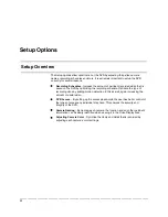
Страница 43: ...n areas General Configure display options alerts intensive recording Frames Set the Images Per Second for each camera Recording Schedule Create custom recording schedules for each channel sensor and special days Sensor Assign sensor names set to Normally Open or Normally Closed Network Assign network settings Administration Set permissions for users export logs adjust HDD storage Information View ...

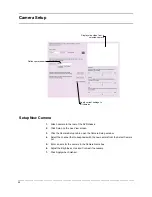
Страница 44: ... the Live View screen 3 Click the Camera Setup tab to open the Camera Setup window 4 Select the channel that corresponds with the new camera from the Select Camera list 5 Enter a name for the camera in the Camera Name box 6 Adjust the Brightness Hue and Contrast if necessary 7 Click Apply when finished Displays live video from a selected camera Define camera name Apply current settings to all came...

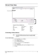
Страница 45: ...tage VivoTek Connecting a Network Device Note Refer to the EQUIP Series Network IP camera user guide for detailed information on setting up that camera using the Honeywell IP Utility application Connecting Manually 1 From the Live View screen click Setup 2 Click the Network Video tab 3 Click the Add Remove Device tab 4 Select your network device from the Device Type list 5 Type a Device Name 6 Typ...

Страница 46: ...the User ID and Password of the device 8 Click Update Assigning a Network Device to a Channel 1 From the Live View screen click Setup 2 Click the Network Video tab 3 Click the Channel Setup tab 4 Click an available channel on the Channel List 5 Type the desired Position Name 6 Select the appropriate network device added previously 7 If the device has PTZ capabilities select the PTZ Camera check bo...

Страница 47: ...en click Setup 2 Click the Network Video tab 3 Click the Audio Setup tab 4 Click an available audio channel on the Channel List 5 Select a network device added previously 6 To record the network audio select the Record Network Audio check box The audio channel will be available on the search screen 7 To access the audio channel from the Live View screen select the Enable Network Video in Live View...

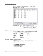
Страница 48: ...ormance of the DVR Displaying More Columns The Camera Configuration tab can be customized to display the information you use most Click Select Column to add or remove specific columns Capture FPS Record FPS Schedule Manufacturer Model IP Address Port Number Resolution Record FPS Frame Rate Codec Quality PTZ Accessing the Device Configuration Menu Use the Fusion interface to access basic network de...

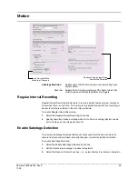
Страница 49: ...Sensor recording is selected in the recording schedule To enable Regular Interval Recording 1 Select the Regular Interval Recording check box 2 Specify how often to take an image when no motion is occurring System can be set to as many as one image per second Enable Sabotage Detection The Camera Sabotage Detection feature will notify users that the field of vision of a camera has been compromised ...

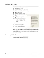
Страница 50: ...lick a Motion Detection Area shape button 7 Drag the mouse over the camera image Tip To create a polygon shape click the mouse at each point and double click to close the shape 8 Click OK 9 Move the sliders to adjust motion sensitivity and the noise filter 10 Define the pre alarm and post alarm recording time for a motion event Pre Alarm 0 50 Seconds The number of seconds the DVR records before mo...

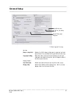
Страница 51: ... stop the beeping Sequence Setting Allows the video out picture to automatically cycle through channels at a set speed Example Cycle through channels 1 6 at four second intervals Display Options Use Full Screen Stretch the Fusion software to use the full monitor screen Display Size Select from available monitor display sizes Use to correctly display video on wide screen monitors Enable Live Record...

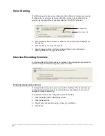
Страница 52: ...ion Activate on Sensor Alarm and or Activate on Sabotage Detection to trigger the audio file Intensive Recording Overview The Intensive Recording Option allows an increase of the Images Per Second and the resolution of any camera recording using sensor activation Enabling Intensive Recording The Intensive Recording option is set up as an All or Nothing This means that once enabled associated with ...

Страница 53: ...n internal speaker on the DVR will sound an alarm Video Loss Alarm Log When video loss occurs the event is recorded in the DVR log Activate Alarm Output Activates the last Relay Output on the DVR when camera loses signal This is 16 for a 16 32 CH DVR and 8 for an 8ch DVR 94BTV Out Setup Analog The DVR features an optional TV Out functionality which allows users to output video from any number of c...

Страница 54: ...elect the Use check box to enable TV Out functionality for the selected port 4 Select each camera to display in the sequence 5 Select an Event Popup check box if desired 6 Define the Event Holding Time the number of seconds the camera displays after an event for selected event types 7 Define the Auto Switching Time the number of seconds between switching of camera for the selected TV Out Port 8 Cl...

Страница 55: ...equencing through cameras Tip When in Multiplexer mode the display can only sequence through one type of screen division eg 4 Channel divisions A D or 9 Channel divisions A and B on a 16 channel Fusion 6 To close the TV Out controls click the Close button Connecting to a Wide Screen Display 1 Click Exit on the Live View screen and select Restart in Windows Mode 2 Right click the Desktop and select...

Страница 56: ... Exit on the Live View screen and select Restart in Windows Mode 2 Right click the Desktop and select Properties 3 Click the Settings tab 4 Click the secondary display and click the Extend my Windows desktop onto this monitor check box Tip Refer to the display documentation for the proper resolution settings 5 Click OK and confirm the change 6 Double click the Fusion Server icon on the Desktop 7 C...

Страница 57: ...hould be 1Vp p Up to 48000Hz Playback in Search Mode Mono Sampling Line In Type requires amplification Data Size per channel 1 Second 1 625 bytes 1 Minute 97 500 bytes 10 Minutes 975 000 bytes 1 Hour 5 850 000 bytes 1 Day 140 400 000 bytes approx 140MB Enabling Audio Recording 1 Click the Audio button on the General tab in Setup 2 Select an audio channel under Capture 3 Click OK Enabling Live Audi...

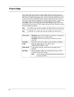
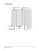
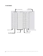
Страница 58: ...PS then the DVR Server will record 7 IPS and users viewing live video remotely will receive 25 IPS on that specific camera Note The Software will not allow the maximum available Frames to be exceeded Note The RED IPS record slider cannot exceed the BLUE IPS capture slider Frame Select Blue Slider Sets the IPS recorded during intensive recording and available for viewing on a remote client PC Red S...

Страница 59: ...____________________________________________________ Document 800 05305 Rev A 59 11 09 Standard Models Reset to Default Settings Sensitivity Video Quality Recording Resolution Frame Select No of Recording Frames Selected Compression Codec Camera Channel ...

Страница 60: ..._____________________________________________________ 60 H 264 Models Reset to Default Settings Video Quality Recording Resolution Frame Select No of Recording Frames Selected Camera Channel Display Time of Selected Channels Output to Video Out Display ...

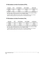
Страница 61: ...s recorded in 720x480 are four times the size of the standard 360x240 When recording at 720x480 each frame assigned to the channel will use 4 of the total frames available IPS Breakdown for Each Resolution PAL Resolution CCTV 400 IPS Model 200 IPS Model H 264 Models 360x288 1CIF 400 IPS 200 IPS 400 IPS 720x288 2CIF 200 IPS 100 IPS 400 IPS 720x576 4CIF 100 IPS 50 IPS 400 IPS D1 Frames recorded in 7...

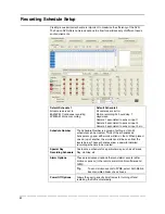
Страница 62: ...ociated to sensor input 3 etc Schedule Number The Schedule Number is a group of settings Up to 32 schedules can be created Think of the schedules as transparency paper with words written on them When placed one on top of another the words can still be seen from the layers below These schedules allow a powerful detailed recording schedule to be created Special Day Recording Schedule Customize a sch...

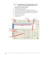
Страница 63: ...g multiple days simultaneously Clicking on Single Day Selection will change the button to Multi Day Selection This enables the user to select multiple days to configure at once Creating a Simple Schedule By Example Creating schedules is easy with a little experience In the following example the steps for creating a simple schedule for cameras 1 to 4 are detailed The schedule will be as follows 1 M...

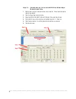
Страница 64: ...Select Sch01 from the Schedule Number drop down list This should already be selected by default 2 Click the Single Day Selection button 3 Select the MON TUE WED THU and FRI days of the week check boxes 4 On the Sch01 line on time selector grid highlight hours 09 17 Click Set 5 Click Camera buttons 1 4 until the green Motion buttons are selected 6 Click Apply to save Step 4 Step 5 Step 1 Step 2 Ste...

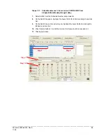
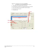
Страница 65: ...pm 8 59am Monday through Friday 7 Select Sch02 from the Schedule Number drop down list 8 On the Sch02 line again highlight the hours 18 23 for 6 00pm midnight and click Set 9 On the Sch02 line on time selector grid highlight the hours 00 08 for midnight to 8 59am and click Set 10 Click Camera buttons 1 4 until the maroon Continuous buttons are selected 11 Click Apply to save Step 8 Step 10 Step 7 ...

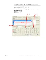
Страница 66: ...1 59pm Saturday and Sunday 12 Select Sch03 from the Schedule Number list 13 Select the SAT and SUN check boxes 14 Clear all other Day of Week check boxes 15 On the Sch03 line on the time selector grid highlight hours 00 23 and click the Set button 16 Click Camera buttons 1 4 until the Green Motion buttons are selected 17 Click Apply to save Step 15 Step 16 Step 12 Step 13 14 ...

Страница 67: ...lso activate Relay Outputs as desired RELAY OUTPUT Relay Outputs can be set to activate when motion alarms or sensor alarms occur The schedule example will be as follows 1 SUN SAT 12AM 11 59PM Cameras 1 and 2 will be activated on Sensor 3 and or Sensor 5 which will then activate Relay Output 7 and 13 2 SUN SAT 12AM 11 59PM Camera 3 will be set to Record on MOTION When motion occurs it will activat...

Страница 68: ...om the Schedule Number list This should already be selected by default 2 Click the Single Day Selection button 3 Select the SUN MON TUE WED THU FRI and SAT check boxes 4 On the Sch01 line time selector grid highlight the hours 00 23 and click Set 5 Click Camera buttons 1 and 2 until the Red Sensor buttons are selected 6 Click Sensor buttons 3 and 5 7 Click Relay buttons 7 and 13 8 Click Apply to s...

Страница 69: ... to record using MOTION When Motion occurs it will activate Relay Output 7 and 10 9 Select Sch02 from the Schedule Number drop down list 10 On the Sch02 line time selector grid highlight the hours 00 23 and click Set 11 Click Camera button 3 until the green Motion button is selected 12 Click Relay buttons 7 and 10 13 Click Apply to save Step 10 Step 11 Step 9 Step 12 ...

Страница 70: ...e Sensor 6 to activate Relay 8 when an Alarm occurs Note This will not cause any cameras to record 14 Select Sch03 from the Schedule Number list 15 On the Sch03 line time selector grid highlight the hours 00 23 and click Set 16 Click Sensor button 6 17 Click Relay button 8 18 Click Apply to save Step 15 Step 14 Step 17 Step 16 ...

Страница 71: ...ng that all hours of the selected day are covered by at least one of the 32 independent schedules vertical axis of schedule grid now look to the lower half of the schedule interface 4 In the Schedule Number selection drop down box select the schedule s that were defined above for the current day and verify in each schedule number that the correct cameras are set to Continuous Motion or Sensor base...

Страница 72: ...ab to open the Sensor and Output Display 3 Click to select NO or NC for the desired sensor 4 Enter the Delay Time to define the number of seconds after the sensor is tripped until the associated relay is activated Tip Associate sensors and relays with cameras when creating a recording schedule 5 Click Apply Enter Custom Sensor Control Names Configure Hybrid IP Sensors HVR NVR upgrade necessary to ...

Страница 73: ...pter 2 Click the Setup button on the Display Screen 3 Click the Sensor tab to open the Sensor and Output display 4 Click Sensor Preset 5 Select the desired camera from the Channel list 6 Select the appropriate Sensor from the list 7 Select the preconfigured PTZ Preset from the list 8 Click Set A list of configured Sensor Presets will display in the box below 9 Repeat for additional sensors 10 Clic...

Страница 74: ...econds the connection will be terminated Emergency Port Used to connect to the Alarm Monitor software Center Port Used to connect to the Fusion remote software This port must be specified in the Fusion Remote Software to connect to the DVR Note Center Port 1025 is not available for remote connections It is used by the ATI VGA management suite Image Port Used to transfer the video to the Fusion rem...

Страница 75: ...regarding the health of the DVR Resolution By setting the resolution low the images will be sent faster however the image quality will be reduced considerably When set to Original full quality video will be sent 720 x 480 NTSC 720 x 576 PAL The Original setting is very bandwidth intensive Transport Setup Transport Rate Throttles the bandwidth on the DVR This option is based on percentages of image...

Страница 76: ...al Log Management The Log Management window provides the user with the options to overwrite log files or schedule log deletion Setup Log Management Options 1 In Setup on the Administration tab click the Log Management button 2 Select the check box to enable the Log File Overwrite option Set Log Overwrite a Select Overwrite and define the size of the log file cache Set Log Cache Size a Select Do No...

Страница 77: ... button 3 Click Add User to open the User Management window 4 Enter the Administrator password and click OK 5 Enter a user name and password 6 Select appropriate permissions 7 Select cameras and audio channels to be hidden from the user 8 Assign a user rank 9 Click OK to save and exit Note Every DVR comes with an Administrative account and Default account loaded on them The Default account should ...

Страница 78: ... DVR Software can only have one user operating the PTZ controls at any given time A user with a higher rank can override another user and then open the PTZ controls 1 Enter Setup 2 Click the Administration Setup tab 3 Click the User Management button 4 Enter the Administrator password and click OK 5 Select a user from the Select User box and click the Update User button 6 Set the user s rank using...

Страница 79: ...e from email account Contact the email administrator for this information if necessary 7 If using a secondary email account select the Use Secondary SMTP Box and complete the SMTP information 8 Click the Test button to check settings 9 Click Apply when finished Users 1 Set up the General tab 2 Click the Users tab 3 Select the type of event to send email on 4 Enter the User Name and Email Address o...

Страница 80: ...Check check box 3 Define the number of minutes 4 Select an Alert Option Beep or Popup Message if desired 5 Click Apply Recording Data Check 1 Set up the General and Users tabs first see above 2 Select the Recording Data Check check box 3 Define the number of hours between data checks 4 Select the Action Method 5 Click Apply SMART Information The SMART Information tab displays Hard Drive informatio...

Страница 81: ...e 6 Select an action method 7 Click Apply Alarm Event 1 Set up the General and Users tabs first see above 2 Select the Use Email Alarm check box 3 Define the number of minutes between recording data checks 4 Select Motion and or Sensor to send and alert on that type of event 5 Click Apply 6 Click Close to return to the Administration tab Data Management Data Management is available for select regi...

Страница 82: ...fication name used by other DVR software to identify the DVR Remote Alarm Monitor FVMS Digital Signature Verifier CBSN Displays the serial number of an internal DVR hardware component PTZ The PTZ Setup enables PTZ cameras creates Presets Tours and adjusts speed settings Many options listed here are features only available on selected cameras Refer to the Advanced PTZ chapter in this manual for des...

Страница 83: ...stant Recording can be used for example when a suspicious object or person is detected and the user wants to flag that section of video for easy retrieval at a later date Activate Instant Recording 1 From the Live View screen double right click on the camera on which to enable instant recording An INSTANT label will be placed on the upper right corner of the video 2 To turn the Instant Recording o...

Страница 84: ...screen 2 Select Restart in Windows Mode 3 Right click the My Computer icon on the desktop and select Explore 4 Double click on Control Panel to open it If Control Panel is not listed double click My Computer to expand the folder tree 5 Double click the Date and Time icon 6 Adjust the date time and time zone 7 When finished close all open windows and restart the DVR by selecting Start Shut Down Res...

Страница 85: ...ounts on multiple DVRs This makes managing a large number of DVRs easy and organized The Central User Management program is run on a computer or DVR that is to be used as the hub This computer or DVR acts as a broadcaster sending out updated information The diagram below provides an overview of how the Central User Management functions User Accounts can be modified from any DVR as well as the Mana...

Страница 86: ...and locks access to the DVR Management and User Management options Exit This option exits the Management Station Software Setting Up the Central User Management Server To set up a Central Management User Server follow these steps 1 Install the Central Management User Software on a computer or DVR 2 Run the software and open Site Management Logging in may be necessary 3 Add one or more DVRs to the ...

Страница 87: ...gement Specify user privileges in the User Management Window The User Management Console has the ability to create edit and delete user accounts Each user account can be assigned different privileges that limit their usage of the DVR system Users can be given administrator privileges by enabling all rights however only the true administrator account can log into the User Management Console 1 Click...

Страница 88: ...enable a DVR to use the Central User Management software follow these steps 1 Click the Administration tab in the Setup Window 2 Click the User Management button 3 Click the Authentication button 4 Enter the IP address of the Authentication Server running the Central User Management software 5 Enter the Server Port used by the Authentication Server Must be between 7000 7100 6 Enter a Site Port tha...

Страница 89: ...ptions that allow easy searching to find a particular section of video From Motion and Sensor indexing to calendar views showing which days have recorded video the DVR is equipped to quickly find what the user is seeking Note 16 Channel model shown below Screen Division Buttons Search Options Play Controls Actual Date Time Search Date Time Hour Minute Control Calendar Button Select Cameras ...

Страница 90: ...inds video Play Plays video Forward Frame Moves video forward one frame Stop Stops video playback Hour Minute Control The Hour Minute Control Bar allows a user to select the Hour and Minute using an easy to use slide bar The user can control the slide bar by clicking and dragging the slider or using the scroll wheel on the mouse Rewind Stop Play Back Frame Forward Frame ...

Страница 91: ...tness of an Image 1 Select a single image to adjust by double clicking on the desired image Multiple images cannot be adjusted at one time 2 Move the Bright slide bar to the right or left to adjust the brightness 3 Reset the brightness by clicking the Bright button Zooming in on an Image 1 Select a single image to adjust by double clicking on the desired image Multiple images cannot be adjusted at...

Страница 92: ... 3 Click the Time Synch button The video will now playback in real time Search Options Overview The Search Options allows the user to find the requested images quickly enhance the image quality and export the video or images in a number of ways Index Search Used to perform a search based on Motion detection and Sensor activation Allows for quickly narrowing down large amounts of recorded video bas...

Страница 93: ...stances would be recorded over The DVR records both hours and allows the user to select which hour to play if necessary To access the lost hour 1 From the Search Display select the Calendar button 2 Select the last day of Daylights Saving time The Daylight Saving option appears 3 Select the Daylight Saving check box 4 Click OK to confirm the date and begin playing the video using standard search f...

Страница 94: ...me AVI AVI image data can be stored uncompressed but it is typically compressed using a Windows supplied or third party compression and decompression module called a codec AVI files save a video clip Analog Out Sends a full screen video signal to the s video port of the DVR 1 From the Search screen click the Save button The Analog Out feature is only available on DVRs with an S Video out 2 Select ...

Страница 95: ... and select Bookmark End 6 Type a name to identify the bookmark in the Title box 7 Enter a memo or notes in the More Information box 8 You may also select additional channels to include video at different locations recorded at the same time 9 Click Create Modify Bookmarks You can modify a previously created bookmark to change the start or end time of the clip add additional comments change the tit...

Страница 96: ...ely remove the device Single Clip Backup Using Bookmark Data Note If you to use bookmark data for the Clip Backup only previously bookmarked data will be included You cannot perform a standard clip backup in conjunction with bookmark data 1 From the Search screen click the Save button 2 Select the drive from the file tree to save data to Hard disk drive removable drive CD DVD drive 3 Click Use Boo...

Страница 97: ...earch 4 Select the Select Time check box to define a specific period 5 Select a sort option sensor motion instant record or select the All Event option 6 Click OK There may be a delay while results are returned Results will be displayed in a column on the left side of the screen Each line represents a segment of video If no results are found NO IMAGE FOUND will appear in the column 7 Once the resu...

Страница 98: ...w how the Preview Search functions The first screen that appears has 24 images displayed Each image represents the first second of each hour If there is no image recorded during that period then nothing will be displayed When an hour is selected by double clicking on the image then a new screen appears with 6 images Each of these images represents a 10 minute segment of video Once a 10 minute segm...

Страница 99: ...search by double clicking on an image to select it 6 images display If needed return to the previous 24 image view by right clicking on an image 4 Refine the search by double clicking on an image to select it 10 images display If needed return to the previous 6 image view by right clicking on an image 5 Double click an image to select the 1 minute segment of video to play A single image displays I...

Страница 100: ...creen Display 4 Drag the mouse on the video display to define a motion region box Resize by dragging the small square boxes located on the outer perimeter of the box 5 Click Start Search the Object Search Filter window will open 6 Select an end date time One hour is the default setting 7 Adjust the sensitivity if necessary 8 Click the OK button 9 Select a motion event from the search results list ...

Страница 101: ...Show Performing a Status Search 1 Select the Status Search button on Search Screen Display 2 Click the calendar icon to select a day 3 Click on an area of the blue recording block Only one camera can be displayed at a time 4 Recorded video from the corresponding camera and time block will display above 5 Use the mouse or arrow buttons to move through recording blocks and view video Cameras Recordi...

Страница 102: ...video recorded prior to version 3 6 Performing a Motion Search 1 Select a camera Motion Search can only be performed on one camera at a time 2 Click the Motion button on the Search screen 3 Click the calendar icon to select a day 4 Adjust the motion level line 5 Adjust the timeline display settings 6 Click the play button to start playback Tip You can drag the blue line on the Timeline or motion l...

Страница 103: ...era in the Getting Started chapter 2 Start the DVR 3 Click the Setup button and select the PTZ Setup tab 4 Select the PTZ camera from the Channel List 5 Select the Pan Tilt Connection to enable the PTZ functions of the camera 6 Once enabled select the appropriate protocol Note Protocols are a set of instructions written by the manufacture of the PTZ cameras that allow software programs such as thi...

Страница 104: ...NGYANG 255RXC DVRX 1000 DYNACOLOR ERAESEEDS CRX 1401 ERNITEC EVERFOCUS EPTZ1000 FASTRAX II FASTRAX IIE FILLTECH DSC 230 PT 201 FINE SYSTEM CRR 1600 FOCVISION KD1602 GANZ ZC PT SERIES HMC 250 HSCP INTER M VSD 640 INTER M VRX 2101 JAVELIN ORBITOR JVC TK C676 C55 KALATEL CYBER DOME KDC KODITEC LG LPT A100L LG LVC A70X S LG LVC M300 310 LG MULTIX LG SPEED DOME MERCER MERIT LI LIN MERIT LI LIN V6 MIC1 ...

Страница 105: ...________________________________________________________________________________________________________ Document 800 05305 Rev A 105 11 09 Advanced PTZ Setup PTZ Signal Type PTZ Protocol List ...

Страница 106: ...ntroller 4 In the Preset options box select a Preset from the list to modify a red box will appear around the Preset 5 Use the controls on the Graphical Controller to move the selected camera to the desired position 6 Enter a Dwell Time and Speed Setting This is used for the Tour 2 function Each preset can have a different Dwell and Speed setting 7 Click the Set button once the camera is in the de...

Страница 107: ... preset sequences This list is only displayed on supported protocols Travel Speed Sets the speed at which a PTZ moves from one Preset position to the next when using Preset Tour 1 Dwell Time Defines the length of time in seconds that a PTZ Tour stays on a Preset Position when using Preset Tour 1 The Honeywell VCL Tour has been updated Preset 1 now obeys configured speed and dwell times and Preset ...

Страница 108: ...n button 4 Using the PTZ Controller move the PTZ in the path of the tour to mimic 5 Click the Stop Position button when finished moving the PTZ around 6 Click OK or Apply to save Viewing the Mimic Tour 1 On the Main Display Screen click the PTZ button to open the graphical controller 2 Click the video display of the desired PTZ camera 3 Click the Tour button The Mimic Tour will activate PTZ Status...

Страница 109: ...for PTZ cameras connected to the DVR The Tour Schedule allows users to schedule tours on specific days of the week and specific hours of the day for multiple PTZ cameras Selected time frames are designated in blue and non selected default frames and shown in white Creating a PTZ Tour Schedule 1 Click the Tour Schedule button on the PTZ Setup tab 2 Select a Day of the Week or Click the Single Selec...

Страница 110: ...Menu Opens the PTZ Camera Menu Select Select an item on the onscreen menu Close Close the PTZ Onscreen Menu Up down The Up and Down buttons on the PTZ controller move through the PTZ menu options Left Right The Left and Right buttons on the PTZ controller move through the PTZ menu options and or highlight options Since every PTZ camera is different the functions of these options can vary slightly ...

Страница 111: ...on is a much more powerful way to control the Camera Using the On Screen Compass 1 Click the Setup button on the main screen 2 Click PTZ Setup 3 Select the On Screen Compass check box to enable the feature 4 Click the Apply button 5 Click the Exit button to return to the main screen 6 Click the PTZ button 7 Control the PTZ by dragging the mouse on the screen in the desired direction A green line w...

Страница 112: ... a different camera on the Main Screen Display Note Eight directions are available only for select protocols Only four of the PTZ Control buttons work for all protocols UP DOWN LEFT RIGHT AUX Buttons The AUX buttons activate different options for each protocol The protocols and their options are defined below VCL Javelin Orbitor HONEYWELL MAXPRO AUX 1 Auto Iris AUX 2 Auto Focus Pelco D Pelco P Kod...

Страница 113: ...Program This ensures the integrity of the data Throughout the backup process the DVR will continue recording without interruption This is the result of the tremendous multiplexing power of the DVR which allows it to perform virtually all functions without disrupting the recording process Nero Express The DVR uses Windows XP Embedded running Nero Express 7 0 to write data to the DVD RW Drive This s...

Страница 114: ...ckup button on the Main Display Screen 2 Select the date or dates to back up video from using the calendar Dates highlighted in blue contain recorded data 3 Select the blocks of time to back up using the Hour Minute Menu Blocks of time with recorded video are highlighted in green Blocks of time selected for backup are highlighted in red 4 Select the drive or drives to save the backup video to usin...

Страница 115: ...Screen 2 Click the Clip Backup tab at the top of the Backup Center window 3 Set the Backup Time and End Time of the video to backup in the Time Setup box 4 Select the Cameras to back up in the Channel Selection box 5 Select the Backup Drive to save the backup video to 6 Check the Include Viewer Check box to include the Proprietary Viewer application 7 Enter pertinent clip information into the Clip...

Страница 116: ...rive button To save to a local drive or partition first rename the location Backup 6 Check the Overwrite on Disk Full check box to overwrite previous scheduled backups when the disk becomes full 7 Click the Save Backup Setting button to save the current backup setting and return to the Main Display Screen Specifying Scheduled Backup Drives In order to use the Scheduled Backup feature one or more s...

Страница 117: ...Windows XP Embedded is far superior to other platforms when running on a LAN The number one reason is security Running the DVR on a secure network is important to prevent unwanted users from gaining access to confidential information Unwanted users can compromise the integrity of the confidential data being stored and viewed and in extreme circumstances can cause irreparable damage to the network ...

Страница 118: ... and Subnet mask appropriate for the network It is recommended to contact the Network Administrator for appropriate IP settings Example Common IP addresses are 10 0 0 25 Common Subnet masks are 255 255 255 0 Note In order to connect to the DVR through a remote LAN connection a static IP address must be assigned If the network assigns the IP address automatically DHCP contact the Network Administra...

Страница 119: ...ned to the Domain The DVR server will query the LDAP server for accounts and authorization levels The DVR server creates groups within Active Directory for each of the permissions on the DVR Simply join a Domain user to these groups to provide access to that function in the DVR DVR access within Active Directory is based on the Site Code within the DVR software This allows an administrator to grou...

Страница 120: ... to be used for LDAP authorization The default will be 100 000 This site code can be used to group DVR s together within Active Directory a Log in to the DVR using the local DVR administrator account non LDAP b Navigate to the Setup Information tab and change the Site Code 3 Log on to the DVR server with the domain account with administrator privileges see above required items If successful the DV...

Страница 121: ... site code 100 000 DVR_HIDE_CAMERA_0XX_100 000 Hides camera XX for DVRs site code 100 000 DVR_INSTANT_100 000 Instant recording access to DVR DVR_PTZ_100 000 PTZ access to DVRs site code 100 000 DVR_PTZEX_100 000 Access to advanced PTZ control DVR_RELAYOUT_100 000 Access to toggle relays from live view DVR_SEARCH_100 000 Access to search on DVRs site code 100 000 DVR_SETUP_100 000 Access to setup ...

Страница 122: ...________________________________________________________________________________________________________ 122 NOTES ...

Страница 123: ...ed security monitoring The Honeywell Video Analytics option is available at the time of ordering for all Fusion III DVRs and requires the factory installed Hardware Performance upgrade Important Notes Fusion channels running Honeywell Video Analytics must be configured to record 10 15 IPS See Frame Setup in the Setup Options chapter of this manual for more information If the Analytics button is mi...

Страница 124: ...s Guide for instructions Note The operators guide is pre installed on the Fusion DVR START Programs Active Alert Server Documentation Operators Guide pdf Add the Fusion Server Login to Honeywell Video Analytics 1 Click Analytics on the Live View screen and click configuration 2 On the File menu click Fusion Administrator Info 3 Enter the Hostname The Hostname is the IP address of the Fusion Server...

Страница 125: ...1 from the POS ID list and then click Add Tip If other software is utilizing POS ID 1 select the next available POS ID number 7 Under Remote Info enter Remote IP 127 0 0 1 Remote Port 18081 8 Select the Match Workstation ID check box 9 Enter the appropriate workstation ID Tip The workstation ID should match the video channel that Honeywell Video Analytics is running on 10 Enter the User and Passwo...

Страница 126: ...ew screen Honeywell Video Analytics Modules Live Monitoring Station the user can view the live processing results Forensics Tool provides an easy to use interface to retrieve relevant data from the database based on the user defined query Report Generator Tool generates statistical event reports from the ActiveAlert server database Configuration Tool allows the user to configure the specific types...

Страница 127: ...rm Schedule 1 Click Setup from the Live View screen 2 Click the General tab 3 Click Video Analysis 4 Click Video Analysis Alerts Setup 3 Select one day of the week or Click the Single Selection Mode button to select multiple days at once 4 Drag the mouse across an Alarm row to select the hours of the day 0 23 5 Click Set Tip Alarm01 will correspond with Index 1 on the Video Analytics Alert List ...

Страница 128: ...o correspond with the alarm schedule 4 Type the Alert String text ie Counted or Entered 6 Select the effects to activate when the Alert String is detected Color Highlight the alert string text with color Beep Activate audible beep Popup Activate popup message window Relay Trigger selected Relay alarm Sensor Associate selected Sensor to trigger Intensive Recording 5 Select the Select POS ID check b...

Страница 129: ...rch button on the Live View screen 2 Click Analysis 3 Select Detail Search and click OK 4 Select Event Text from the Search Data Type list and click the Add button 5 Select events from the Registered Events list and click the button When done click OK Tip To search for an event at a specific date or time use the Date Edit section of the Event Search window 6 Click Search A list of events will appe...

Страница 130: ...________________________________________________________________________________________________________ 130 NOTES ...

Страница 131: ... Password protected Easy to use graphical interface Basics 75 users can access the Web DVR simultaneously The Web Viewer is an easy secure way to view live video from virtually any computer with an internet connection using Microsoft Internet Explorer To log in to the DVR server from the Web Viewer a user account must be made for the user This ensures that only authorized users are allowed to log ...

Страница 132: ...DVR Using Web Viewer 1 Open Microsoft Internet Explorer 6 2 Enter the IP address of the DVR into the Address Bar 3 When attempting this for the first time you will be asked to accept an Active X installation Select Yes to this Note If you receive a message saying Internet Explorer security settings do not allow you to download Active X components then you will need to adjust the browser security s...

Страница 133: ...ys back the exported video in its proprietary format Video saved in this format is extremely difficult to tamper with and therefore is the ideal solution when law enforcement and legal departments are involved This video cannot be read by any other viewer The Proprietary Viewer is essentially the Search portion of the DVR software For detailed explanation of these functions refer to the Search Cha...

Страница 134: ... at a later date Click the Next button 6 Click the Finish button Loading Video from DVD ROM or Hard Drive 1 Open the Proprietary Viewer program by selecting Start Programs Fusion Proprietary Viewer Proprietary Viewer 2 Select Backup Search see the Performing a Basic Search section and the Total Backup Search window opens 3 Click the Chose Time to Search tab 4 For CD ROM data select the appropriate...

Страница 135: ...into the CD ROM Do not install on the DVR 2 Select the Digital Verifier option to begin installation When the Welcome screen appears click Next 3 When the Setup Complete window appears click Finish Installation is complete Using the Digital Verifier 1 Open the Digital Verification program by selecting Start Programs Fusion Digital Verifier Digital Signature Verifier 2 Click the Browse button to lo...

Страница 136: ...een instructions 3 Click the Finish button to complete the installation Configuring the DVR To enable the Alarm Monitor on the DVR follow these steps 1 Enter Setup and click the Recording Schedule tab 2 Assign the desired sensors to the desired cameras Refer to the Recording Schedule section of this manual for in depth instructions on how to do this 3 Enable Sensor Event and or Motion Event in the...

Страница 137: ...n the Alarm Monitor Window on the Client PC Start Programs Fusion Alarm Monitor Alarm Monitor 2 Click New in the DVR List and enter the site code site name and IP Address of the DVR in the Site Edit window Click Save Note The site code can be found under the Information tab in the Setup Menu 3 Click the Tools Menu and select Setup 4 Confirm that the Listen Port in the Configuration Window is set t...

Страница 138: ...ect a DVR from the Server list under Filter Options 2 Select the Date to include 3 Select the type of Events to include 4 Select the event levels Review Dismiss Critical Default 5 Click the On button to display filtered event listings DVR List Video Display Zoom Thumbnails Event List Memo Text Box Event Type Event Level Level Buttons Save Memo Edit Memo ...

Страница 139: ... play controls to locate the desired video 3 Select the Continue Playing check box to watch all recorded events When not selected playback stops at the end of the alarm event 4 Select the Same Camera check box to watch all events recorded by a single camera 5 Click Apply after making any changes Export Video 1 Double click an event listing to open the Search window 2 Use the play controls to locat...

Страница 140: ...n to this is accessing Setup Only one user is allowed to access setup at any given time The Frames per Second passed to the Remote Client varies greatly depending on the connection type and speed In order to log in to the DVR server a user account must be made for the user This ensures that only authorized personnel are allowed to log in In addition each user can be assigned different privileges t...

Страница 141: ...ments are the minimum requirements for any system receiving data from a DVR using H 264 hardware compression Pentium Core2 Duo or equivalent 1GB System Memory DirectX 9 0c or Higher 512MB Video Card ATI or Nvidia Preferable Internet or LAN Connection 512k or faster preferable Slower connection may work with reduced performance and frame rates TCP IP Installed Microsoft Windows 7 Vista or XP Operat...

Страница 142: ...al is not received by that time the connection is dropped Center Port Used by the DVR to transfer the connection data Image Port Used by the DVR to transfer the image data Search Port Used by the DVR to transfer the search data 1 Enter Setup on the DVR 2 Click the Network tab 3 Clear the Disable Remote Control check box Note If a Firewall is used it may be necessary to adjust the port settings on ...

Страница 143: ...n the Site Info window 3 Enter the Site Code and Site Name The Site Code can be found on the Information tab on the Fusion DVR 4 Enter the IP Address of the DVR server By default the DVR is set to connect using DHCP 5 Enter the Center Port This setting is specified on the server on the Network tab 6 Click OK 7 Click on the newly created connection and enter the username and password 8 Click Connec...

Страница 144: ...must be made for each user This ensures that only authorized personnel are allowed to log in In addition each user can be assigned different privileges that allow them or deny them access to different functions Configuring the Server for Remote Connection 1 Enter Setup on the DVR 2 Click the Network tab 3 Clear the Disable Remote Control check box Note If you are using a Firewall it may be necessa...

Страница 145: ...res Disk Free Space and Storage Failures Enable custom Voice Warning on Failure alert Detailed status screen provides the following information o DVR Information including last Health Check time Total of channels recording DVR software version running current working drive and disconnected time o Video and Recording information including the recording status of each camera channel and whether or n...

Страница 146: ......

Страница 147: ...8 360x288 PAL Image Compression MJPEG Average File Size Analog 360x240 3 5k 720x240 4 8k 720x480 7 12k Video Input 16 Looping Outputs 75Ω Terminations 16 Composite Outputs RCA 4 Max IPS Per Channel 30 IPS NTSC 25 IPS PAL Motion Detection Up to 5 Regions Per Channel Adjustable Sensitivity Remote Operation Full Remote Control through PSTN ISDN ADSL LAN and TCP IP Remote Software Compatible with Micr...

Страница 148: ...0 360x240 NTSC 720x576 720x288 360x288 PAL Image Compression Proprietary MJPEG MPEG4 H 264 Average File Size Analog 360x240 3 5k 720x240 4 8k 720x480 7 12k Video Input 8 16 32 16 32 Looping Outputs 75Ω Terminations 8 16 32 16 32 Composite Outputs RCA 1 1 1 4 1 Max IPS Per Channel 30 IPS NTSC 25 IPS PAL Motion Detection Up to 15 Regions Per Channel Adjustable Sensitivity Remote Operation Full Remot...

Страница 149: ...esolution Analog 720x480 720x240 360x240 NTSC 720x576 720x288 360x288 PAL Image Compression H 264 Average File Size Analog Video Input 8 16 Looping Outputs 75Ω Terminations 8 16 Composite Outputs RCA 1 1 Max IPS Per Channel 30 IPS NTSC 25 IPS PAL Motion Detection Up to 15 Regions Per Channel Adjustable Sensitivity Remote Operation Full Remote Control through PSTN ISDN ADSL LAN and TCP IP Remote So...

Страница 150: ...410 200 Honeywell Security Group Deutschland Johannes Mauthe Straße 14 D 72458 Albstadt Germany www honeywell com security de 49 74 31 8 01 0 Honeywell Security Group France Immeuble Lavoisier Parc de Haute Technologie 3 7 rue Georges Besse 92160 Antony France www honeywell com security fr 33 0 1 40 96 20 50 Honeywell Security Group Italia SpA Via della Resistenza 53 59 20090 Buccinasco Milan Ital...

Отзывы: