Chapter 5 - Building ControlNet Trunk Cables
The cut adjustments described in the following procedure must be precise. Adjustments as small
as 1/12 to 1/8 of a turn can make the difference between a perfect and an imperfect cut.
Do not over-tighten the screws of the cable strip tool. The blades should not bend, shift, or
penetrate the calibration tool.
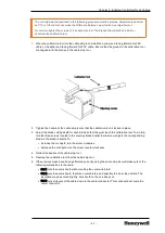
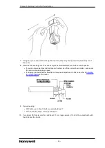
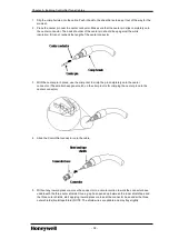
1. Place the calibration tool into the cable strip tool. Install the narrow end facing forward for FEP
cable or the wider end facing forward for PVC cable. Ensure that the groves in the calibration tool
are aligned with the blades in the cable strip tool.
2. Tighten the handle of the cable strip tool so that the calibration tool is locked in place.
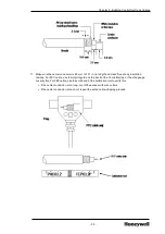
3. Adjust the blade cutting depth for each blade so that they just touch the calibration tool. To do this,
turn the three screws located in the memory-blade holder. Each screw adjusts the corresponding
blade in the blade cassette. To:
l
increase the cut depth, turn the screw clockwise
l
decrease the cut depth, turn the screw counter-clockwise
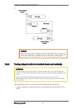
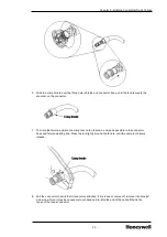
4. Retract the handle of the cable strip tool.
5. Remove the calibration tool from the cable strip tool.
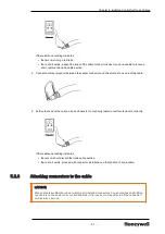
6. If the previous steps have been performed correctly, using the cable strip tool will make cuts of the
following dimensions in the cable:
l
Cut 1 cuts the outer sheath without cutting the outer wire braid.
l
Cut 2 cuts the outer sheath, the three outer shields, and possibly the inner tape shield. The
insulation may be scored slightly, but should not have a deep cut.
l
Cut 3 cuts all layers of the cable down to the center conductor. This cut should not score the
center conductor.
- 27 -

