background image

E

XPERION

PKS

R

ELEASE

515

ControlNet Installation Guide

EPDOC-XX25-en-515A

November 2019

Содержание Experion PKS

Страница 1: ...EXPERION PKS RELEASE 515 ControlNet Installation Guide EPDOC XX25 en 515A November 2019 ...

Страница 2: ...al Sàrl While this information is presented in good faith and believed to be accurate Honeywell disclaims the implied warranties of merchantability and fitness for a purpose and makes no express warranties except as may be stated in its written agreement with and for its customer In no event is Honeywell liable to anyone for any direct special or consequential damages The information and specifica...

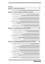
Страница 3: ...out the ControlNet PCIC Card 10 3 1 1 Compliance to European Union Directives 11 3 1 2 Component handling guidelines 12 3 1 3 About PCIC card drivers 12 3 2 Installing the PCIC Card 12 3 2 1 Prerequisites 12 3 2 2 Accessing the expansion slots 13 3 2 3 Inserting the PCIC card 13 Chapter 4 ControlNet Network Component Installation 14 4 1 Preparing to Install ControlNet Components 14 4 1 1 Prepare f...

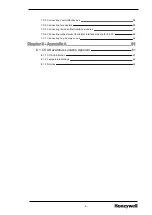
Страница 4: ...cal shorts and continuity 36 5 2 3 Attaching connectors to the cable 37 5 2 4 Testing finished cables 40 Chapter 6 Testing ControlNet Trunk Cables 41 6 1 Preparing to Test ControlNet Trunk Cables 41 6 1 1 Before you begin 41 6 1 2 When to use these tests 41 6 2 Testing using an Ohmmeter 41 6 2 1 Testing for electrical shorts and continuity using an ohmmeter 41 6 3 Testing using a Time Domain Refle...

Страница 5: ...ting to ControlNet Interface modules 57 7 3 6 Connecting to the Server ControlNet Interface module for the PC 58 7 3 7 Connecting Tap Dummy Loads 59 Chapter 8 Appendix A 61 8 1 CSA Hazardous Location Approval 61 8 1 1 CSA Certification 61 8 1 2 Temperature Ratings 62 8 1 3 Notices 62 5 ...

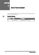
Страница 6: ...ent provides guidelines and procedures for installing ControlNet network components and making and testing ControlNet cables 1 1 Revision History Revision Date Description A November 2019 Initial release of the document 6 CHAPTER 1 ...

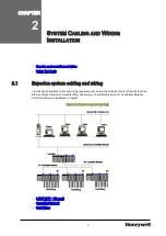
Страница 7: ...ur Experion system s cable and wiring requirements can be broken down into four basic categories Ethernet Plant Information Network PIN Supervisory ControlNet Network I O ControlNet Network and Field Wiring as illustrated in Figure1 Figure 2 1 Experion system topology l LAN TCP IP Ethernet l ControlNet Network l Field Wiring 7 CHAPTER 2 ...

Страница 8: ...o begin installing your ControlNet network refer to Before You Begin in this guide 2 1 3 Field Wiring As with any control system field wiring see figure in all its forms provides the vital link between the I O modules and the process connected sensing measurement and control devices Installation of field wiring is NOT included in the procedures provided by this guide For information concerning l P...

Страница 9: ...ocumentation Before installing any Experion cabling or wiring obtain all available and pertinent documentation This should include all documentation supplied by Honeywell your site s engineering documentation and that from any additional third party suppliers whose products are involved in this installation Additionally you should obtain any applicable regulatory documentation that applies to your...

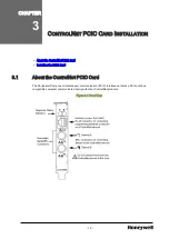
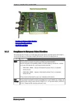
Страница 10: ...ard l Installing the PCIC Card 3 1 About the ControlNet PCIC Card The Peripheral Component Interconnect communication PCIC interface card lets a PCI Local bus compatible computer communicate directly with other ControlNet products Figure 3 1 Front View 10 CHAPTER 3 ...

Страница 11: ...to meet Council Directive 89 336 EEC Electromagnetic Compatibility EMC and the following standards in whole or in part documented in a technical construction file l EN 50081 2EMC Generic Emission Standard Part 2 Industrial Environment l EN 50082 2EMC Generic Immunity Standard Part 2 Industrial Environment This product is intended for use in an industrial environment Low Voltage This product is tes...

Страница 12: ...approved wrist strap grounding device l Do not touch the connector pins l Do not touch circuit components on the card l If available use a static safe workstation l When not in use keep the card in its static shield box or bag ATTENTION Remember a computer with ac power disconnected is not a grounded object 3 1 3 About PCIC card drivers The following releases of Rockwell Software s RSLinx include ...

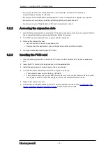
Страница 13: ...slot s expansion cover on the back rear bracket of the computer 4 Go to the next section Inserting the PCIC card 3 2 3 Inserting the PCIC card 1 Use the following procedure to insert the PCIC card into the computer s PCI local bus expansion slot 2 Insert the PCIC card into the edge connector for the selected slot 3 Install the expansion slot screw to secure the card in its slot 4 Turn ON the power...

Страница 14: ...trolNet network refer to the Control Hardware Planning Guide 4 1 3 Agency approval For a listing of agency approvals and specific details concerning these approvals refer to the Experion specifications 4 1 4 Planning All ControlNet network planning activities should be completed before you begin installation For more information concerning planning activities refer to your site documentation and t...

Страница 15: ...hould be applied when mounting taps l There is no minimum trunk cable length requirement between taps Adjacent taps can be connected without a trunk cable at all using a barrel connector TC MC3BNC l Make sure the mounting location is convenient for your cable routing l Make sure the mounting location does not cause any cable bend radii to exceed the limits given in Installing Trunk Cable l Do not ...

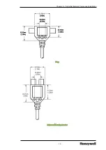
Страница 16: ...Chapter 4 ControlNet Network Component Installation Y tap Universal Mounting Bracket 16 ...

Страница 17: ...rovided by the body holes Once you have mounted your taps you can discard any unused universal mounting brackets CAUTION Do not allow any metal portions of the tap such as the universal mounting bracket screws or connectors to contact any conductive material This contact could cause noise on the network To mount the taps 1 If you are using l the through body hole mounting method go to Step 4 l a u...

Страница 18: ...Chapter 4 ControlNet Network Component Installation 4 Mount the tap and bracket if used to a suitable fixture using the appropriate method DIN Rail Mounting Flat Surface Mounting 18 ...

Страница 19: ... apply identification to your drop cables For more information regarding drop cable identification refer to the Planning Guide ControlNet Configuration Planning Your Taps Planning for drop cable identification Identifying the drop cables from the taps you install makes locating system parts and troubleshooting the system much easier Drop cable labels are included with each tap kit 19 Chapter 4 Con...

Страница 20: ... either the model 9904 RPT or the model 9904 RPTD l Air flow in out of the air holes on the top and bottom of the repeater for proper ventilation must not be impeded Make sure there is a minimum of 5 1 cm 2 in from surrounding equipment l For proper ventilation air flow through holes on the top and bottom of the repeater must not be blocked Make sure NEMA enclosures must be employed in environment...

Страница 21: ... see Installing Repeaters Rules in this section and Mounting dimensions for repeaters provided 4 3 3 Grounding your repeater Keeping the ground lead as short as possible use a 14 AWG wire to connect the repeater to the ground bus Also refer to Power Ground Compliance in the Control Hardware Planning Guide 21 Chapter 4 ControlNet Network Component Installation ...

Страница 22: ...eater For information concerning connecting ControlNet cables to your repeater s refer to Connecting to repeaters in this guide 4 3 5 Connecting power and relay circuitry CAUTION If you are using DC to power the repeater L1 is positive and L2 N is negative See Step 2 of the following procedure 1 Remove the terminal strip cover 22 ...

Страница 23: ...2 Connect power to the repeater 3 If you are l using the fault relay terminals go to Step 4 l not using the fault relay terminals go to Step 5 23 Chapter 4 ControlNet Network Component Installation ...

Страница 24: ...Chapter 4 ControlNet Network Component Installation 4 Connect your relay circuitry to the fault relay terminals 5 Replace the terminal strip cover 24 ...

Страница 25: ...d trunk cable and connectors cable stripping and connector crimping tools and test equipment to test the cables after assembly Honeywell provides the following to aid you in the construction of your own cables l ControlNet certified trunk cable ABREPLACE TC KCC900 ABREPLACE available on a reel in 275 meter 900 feet lengths l Trunk Cable Connectors TC MC1BNC packaged two to a set one for each end l...

Страница 26: ...able is bad o You minimize time lost building individual trunk cable sections from bad raw cable l Disadvantages o Not knowing where in the cable s length it is bad nor how many bad spots it may have o You must install temporary connectors onto both ends of the raw cable to perform the test o It can be difficult to accurately test very long lengths of cable due to its greater inherent attenuation ...

Страница 27: ...e blade cutting depth for each blade so that they just touch the calibration tool To do this turn the three screws located in the memory blade holder Each screw adjusts the corresponding blade in the blade cassette To l increase the cut depth turn the screw clockwise l decrease the cut depth turn the screw counter clockwise 4 Retract the handle of the cable strip tool 5 Remove the calibration tool...

Страница 28: ...rsing and replacing the cutting blades 1 Use a screwdriver to lift the memory blade holder and swing it back 2 Slide the memory blade cartridge out of the strip tool 28 Chapter 5 Building ControlNet Trunk Cables ...

Страница 29: ...e go to Step 5 4 Flip the memory blade cartridge and slide it back into the strip tool Skip Step 5 and go to Step 6 5 Align the memory blade cartridge the side with the raised notches to the raised area on the inside of the strip tool and slide the new memory blade cartridge in The blades should be on top as you slide the cartridge in 6 Swing the memory blade holder closed 29 ...

Страница 30: ...appropriate memory blade holder for the types of cable you are stripping PVC or FEP 1 Lift the latches on the memory blade holder and swing back the holder 2 Snap the memory blade holder off the rod and remove it from the strip tool 3 Position the appropriate memory blade holder on the rod and snap the holder into place 4 Swing the memory blade holder closed 30 Chapter 5 Building ControlNet Trunk ...

Страница 31: ...hen cutting cable sections make them long enough to route from one tap to the next with sufficient slack so that the bend radius does not exceed the defined requirements See Wiring external to enclosures in this Guide for more information 1 Verify that you have the proper memory blade holder installed for the type of cable you are using PVC CL2 or FEP CL2P Refer to Changing the memory blade holder...

Страница 32: ...s the center conductor that will be exposed when the cable is stripped 3 Lock the cable into place by moving the chamber gauge ring forward until it meets the cable with slight resistance The gauge moves two rollers toward the cable and regulates the depth of the cut The gauge will click as it moves from one stage to the next 32 Chapter 5 Building ControlNet Trunk Cables ...

Страница 33: ...g forward a notch the strip tool makes a deeper cut into the cable On your last repetition of Steps 3 and 4 apply sufficient pressure on the chamber gauge ring to ensure the ring has reached the last stage 6 After you have moved the chamber gauge ring to the last position and turned the strip tool the final time move the chamber gauge ring backward to release the strip tool and remove it from the ...

Страница 34: ... wire cutters and repeat the entire cable stripping process l If stripping problems persist the strip tool may need adjustment In this case refer to Adjusting the cutting blades in this Guide 9 If you are using l FEP cable go to Step 10 before completing Step 11 l PVC cable skip Step 10 and go to Step 11 10 For plenum FEP cable cut off an additional 3 1 mm approximately 1 8 in of the outer sheath ...

Страница 35: ...residue For PVC cable use the imprint guide on the back of the ControlNet tap or the strip gauge to verify this For FEP cable use the small end of the calibration tool to verify this l If the center conductor is too long cut off the excess with wire cutters l If the center conductor is too short repeat the entire cable stripping process 35 ...

Страница 36: ... and stripped lengths of raw trunk cable for electrical shorts and continuity This test will be repeated once the connectors have been attached to both ends Other more elaborate testing for structural return loss such as with a Time Domain Reflectometer TDR may also be performed but are more appropriate after your trunk cables have been built Before attaching connectors to your trunk cable test fo...

Страница 37: ... 3 At the other end of the cable use an ohmmeter or continuity tester to test for electrical continuity If the resistance reading indicates l there is no short discard the trunk cable section l that a short exists proceed with connector installation on that section of trunk cable 5 2 3 Attaching connectors to the cable CAUTION Many network problems are due to improperly installed connectors You sh...

Страница 38: ...crimp the pin completely onto the center connector The smaller hexagonal notch on the crimp tool is for crimping the center pin onto the center connector 4 Slide the ControlNet connector onto the cable 5 Without any inward pressure move the connector in a circular motion to work the connector base underneath the three outer shields Once a gap has opened up between the inner shield tape and the thr...

Страница 39: ...crimp tool on the ferrule as close as possible to the connector base and ferrule meeting line Press the tool tightly around the ferrule until the crimp tool allows release 8 Pull the connector to verify that it is securely attached If it is loose or comes off remove it and install a new one Note it may be necessary to cut back and re strip the end of the cable if that is the cause of the loose con...

Страница 40: ...ng them to a new or established ControlNet network For finished cable testing refer to this section Testing ControlNet Trunk Cables l Preparing to Test ControlNet Trunk Cables l Testing using an Ohmmeter and l Testing using a Time Domain Reflectometer TDR 40 Chapter 5 Building ControlNet Trunk Cables ...

Страница 41: ...le segments from certified raw cable or l when troubleshooting your ControlNet network and a cable segment is determined to be suspect 6 2 Testing using an Ohmmeter This procedure is used to test completed sections of trunk cable for electrical shorts and continuity It is identical to the procedure performed after cutting and stripping raw cable lengths except that the connectors have now been att...

Страница 42: ...mmeter or continuity tester to test for electrical continuity If the resistance reading indicates l there is no short replace the trunk cable section l that a short exists proceed with connector installation on that section of trunk cable 4 If the cable passes continuity testing it should then be further tested using a TDR or return loss meter for 75 ohm impedance at 10Mhz CAUTION Replace the trun...

Страница 43: ...s 0 to 60 dB 0 dB or Sensitivity Return Loss Fine 0 dB or Sensitivity Feet Div Red X10 X100 X10 Feet Div 50 to 5 5 Noise Filter Out Position Fine Base Line in Center Intensity As required Focus As required Distance 000 Impedance 50 Ohms Out Impedance 75 Ohms In Impulse Width 100 nsec In or Short Pulse Impulse Width 100 nsec Out or Medium Pulse Impulse Width 1000 nsec Out or Long Pulse Cable Dielec...

Страница 44: ...ing indicating that the minimum bend radius was exceeded reject the cable l Do not compromise on the accuracy of the test terminator This test procedure depends on the delta difference between the terminator and the cable section under test 6 3 1 To test each length of cable 1 With no cable connected verify that your TDR screen appears as shown Settings are l X10 5ft Div l 0 dB 0 dB Loss 2 Connect...

Страница 45: ...Attach and detach a terminator from the loose end of the cable several times to verify that it is the returned pulse and not the transmitted pulse in the center of the screen 5 With the terminator off and using the Return Loss fine control and 0 dB Set if necessary adjust the return pulse to three divisions high while keeping the base line on the horizontal center line Your screen should appear as...

Страница 46: ...ator 6 Connect the selected terminator to the free end of the cable under test Your screen should appear as shown in either the following figures If your settings are l 2 m 6 5 ft example l X10 5ft Div l 0 dB 4 dB Loss l Terminator connected 46 Chapter 6 Testing ControlNet Trunk Cables ...

Страница 47: ...dB control to this new calculated setting For example l zero 0 on Main zero 0 on Fine 30 on Main 4 on Fine l zero 0 on Main 5 on Fine 30 on Main 9 on Fine 8 Adjust the Position and Fine controls until the left and right base lines are on the center line Your screen should appear as shown in one of the following figures If your settings are l 2 m 6 5 ft example l X10 5ft Div l 30 dB 8 dB Loss l Ter...

Страница 48: ...f the return pulse is three 3 or more divisions from the base line in either direction Then the section of ControlNet trunk cable is Rejected If the return pulse is less than three 3 divisions Then the section of ControlNet trunk cable is Accepted 48 Chapter 6 Testing ControlNet Trunk Cables ...

Страница 49: ...ControlNet trunk cable is Rejected If the terminator is producing a trace such as the following Then the terminator is Rejected 10 Tag all rejected ControlNet trunk cable sections as rejected failed and take all necessary steps to replace them ATTENTION If Steps 1 through 8 are performed very carefully Step 9 can be repeated many times for the same length of ControlNet trunk cable without any adju...

Страница 50: ...Table 2 lists the pre built cables available from Honeywell Component Type Model Number 1 meter trunk cable with connectors PVC CL2 TC KCCX01 3 meter trunk cable with connectors PVC CL2 TC KCCX03 10 meter trunk cable with connectors PVC CL2 TC KCCX10 30 meter trunk cable with connectors PVC CL2 TC KCCX30 50 meter trunk cable with connectors PVC CL2 TC KCCX50 100 meter trunk cable with connectors P...

Страница 51: ...according to Honeywell purchase specification 51192416 The cable has UL NEC rating CMR or CL2R as well as CSA CEC rating CMR and passes the UL 1666 Vertical Riser flame test The cable jacket is marked with ControlNet and UL CL2R or CMR or C UL CMR approval information Cable minimum bend radius is 3 inches Temperature rating is 30 to 75 degrees C Other types of non standard trunk cable some with FE...

Страница 52: ...and the system is ON LINE For example if the A channel is faulty and requires troubleshooting DO NOT disconnect anything on the B channel trunks drops terminators while the system is ON LINE DO NOT disconnect the media trunks drops terminators of single media networks while the system is ON LINE All ControlNet BNC connections require a push on twist and lock snap sequence Connections not locked sn...

Страница 53: ...tion of the node along the trunk cable CAUTION The taps on the ends of the segment have only one cable attached to them This leaves an open or unterminated end on the segment Signals transmitted along the cable will reflect off these unterminated ends and interfere with transmission The trunk terminator is used to eliminate these reflections 1 Connect one end of the trunk cable section to one of t...

Страница 54: ...teps 1 and 2 at the other end of the ControlNet segment 7 3 3 Connecting ControlNet devices After connecting trunk cables to taps and terminating the segments per previous topics in this section you may now connect ControlNet compatible devices chassis installed interface modules repeaters etc to the drop cables 54 ...

Страница 55: ...on the ControlNet device If the ControlNet Node supports then non redundant ControlNet cabling Cable A only only one drop cable may be connected to the node redundant ControlNet cabling Cable A and Cable B two drop cables may be connected to the node one from the tap on Cable A and one from the tap on Cable B For details concerning the connection of ControlNet devices to the trunk cable via the ta...

Страница 56: ...e straight or right angle connector of the designated tap on the first segment Segment 1 2 Remove and discard the dust caps from the repeater BNC jacks 3 Connect the designated tap drop cable s straight or right angle connector to the BNC connector on the repeater labeled as 1 4 Remove and save the dust cap located on the straight or right angle connector of the designated tap on the second segmen...

Страница 57: ... cables to the PCIC card in your Experion server refer to Connecting to the Server ControlNet Interface module for the PC 1 Remove and save the drop cable s dust cap located on the straight or right angle connector 2 Connect the tap s straight or right angle connector to your CNI If your ControlNet module supports Connect the drop cable s connector non redundant media only models TC CCN014 to the ...

Страница 58: ...dant media connect the tap drop cable to the BNC connector labeled channel A Channel B is left open If the ControlNet network is redundant connect all devices on the network to the same cable for the same channel All channel A connectors connect to one cable and all channel B connectors connect to the other Also make sure you follow established conventions and standards for identifying drop cables...

Страница 59: ... to the ControlNet B BNC connector on the PCIC card in the computer In both redundant and non redundant ControlNet configurations do not mix A and B connections Follow established conventions and standards for identifying drop cables as described in the Planning Guide ControlNet Configuration Planning Your Taps Planning for drop cable identification 7 3 7 Connecting Tap Dummy Loads CAUTION A Tap D...

Страница 60: ...e of a ControlNet tap TDL s are used to properly terminate unconnected drop cables e g spares for future expansion local service connector etc To connect a Tap Dummy Load 1 Remove and save the drop cable s dust cap located on the straight or right angle connector 2 Connect the Tap Dummy Load to the drop cable connector 60 ...

Страница 61: ...Temperature Ratings l Notices 8 1 1 CSA Certification To comply with CSA certification for use in hazardous locations the following information becomes a part of the product literature for this CSA certified industrial control product l This equipment is suitable for use in Class I Division 2 Groups A B C D or non hazardous locations only l The products having the appropriate CSA markings that is ...

Страница 62: ...ision 2 l Do not replace components unless power has been switched off or the area is known to be non hazardous l Do not disconnect equipment unless power has been switched off or the area is known to be non hazardous l Do not disconnect connectors unless power has been switched off or the area is known to be non hazardous Secure any user supplied connectors that mate to external circuits on this ...

Страница 63: ...f any may be found in the materials accompanying the product in the documents or files accompanying such third party materials in a file named third_ party_licenses on the media containing the product or at http www honeywell com ps thirdpartylicenses Documentation feedback You can find the most up to date documents on the Honeywell Process Solutions support website at http www honeywellprocess co...

Страница 64: ...te https www honeywellprocess com en US contact us customer support contacts Pages default aspx Training classes Honeywell holds technical training classes that are taught by process control systems experts For more information about these classes contact your Honeywell representative or see http www automationcollege com 64 ...

Отзывы: