


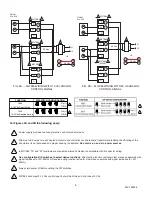


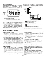


FIG. 9A — ML7984 WIRING WITH 10 Vdc ANALOG
CONTROL SIGNAL
FIG. 9B — ML7984 WIRING WITH 20 mA ANALOG
CONTROL SIGNAL
FUNCTION DIP SWITCH CONFIGURATION
1000
2-10 Vdc Direct Acting
1 2 3 4
1010
10-2 Vdc Reverse Acting
1 2 3 4
On (1)
Off (0)
On (1)
Off (0)
4
5
4
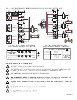
For Figures 9A and 9B the following apply:
Power supply provides overload protection and disconnect means.
Allow up to 0.5 amps for each device. Actuators and controller can share same transformer providing the VA rating of the
transformer is not exceeded and proper phasing is observed.
Do not mix a.c. and d.c. power sources.
In ML7984,“T5” and “W” terminals are connected internally. Device is compatible with 3 conductor wiring.
Use configuration DIP switches to select device functions:
Direct acting function (actuator stem moves downwards with
signal increases to 10V/20mA) or Reverse acting function (actuator stem moves upwards with signal increases to 10V/
20mA).
Always turn power off before setting the DIP switches.
ML7984 will accept 0-10 Vdc control input, but will be at the end of stroke at 2 Vdc.
1
2
3
4
5
6
95C-10939-4
6
3
2
1
T5
T6
L1
L2
2
2
3
3
24 Vac
28 Vdc
ML7984
ML7984
ML7984
R
R
R
W
W
W
C
C
C
T5
T6
T6
T6
T5
T5
OR
SIGNAL
SOURCE
3
1
T5
T6
L1
L2
2
28 Vdc
ML7984
R
W
C
T5
T6
OR
SIGNAL
SOURCE
C
R
W
T5
T6
3
2
ML7984
3
2
ML7984
(SLAVE)
R
W
C
T5
T6
24 Vac
5


