


SPECIFICATIONS
IMPORTANT
The specifications given in this publication do not include normal
manufacturing tolerances. Therefore, an individual unit may not
exactly match the listed specifications. Also, this product is tested
and calibrated under closely controlled conditions and some minor
differences in performance can be expected if those conditions are
changed.
Operating Environment:
Operating Ambient Temperature: 0
O
C to 55
O
C (32
O
F to 130
O
F)
measured at the actuator
Shipping Temperature: -40
O
C to +65
O
C (-40
O
F to 150
O
F)
Relative Humidity: 15% to 95% up to 40
O
C (104
O
F), non-con-
densing atmosphere NEMA-3R/IP54 cover for outdoor
installation
Acoustic Noise:
55 dBA maximum Sound Pressure Level at 1 m (39") distance
Electrical Ratings:
Power supply/consumption:
24 V (+10%, -15%), 50/60 Hz or 28 Vdc +/- 10%,
6 VA (Running), 12 VA (Valve seating)
Inputs:
ML6984 - 25 mA 24 Vac (5-wire mode only)
- 500 mA (valve seating 3-wire mode)
- Minimum Signal Input Duration: 100 ms
ML7984* - 2 -10 Vdc (1 mA); 4-20 mAdc
*May be used with 0-10 Vdc input but valve will be closed at 2
Vdc
Input Impedance for the ML7984:
Voltage Source — 20 K ohms
Current Source — 237 ohms
Shipping Weight:
Approx. 1 kg (2.2 lbs)
Accessories/Parts:
272629A - Mounting adapter for V5045 valves
43196000-001 - High temperature mounting kit for hot media
272630D - Electronic position feedback low voltage auxiliary switch
272822 - Resistor kit for multiple actuator Series 90 application
and for ML7984 to replace the old ML784 (4-20 mA)
272775 - Replacement motor brush kit
40003793-005 - Mounting hardware bag assembly
Mechanical Ratings:
Stroke—Between 1/2
”
(13 mm) and 1
”
(25 mm), self-adjusting
Bonnet—1 3/8
˝
(35 mm) for V5011/13 valves up to 3
˝
(DN80)
Stem Coupling— 1/4-28 UNF thread
Stroke Timing— Nominal 63 seconds for 3/4" stroke
— Proportional to stroke length at 24 Vac
Closing Force— 710 N (160 lbs) minimum at 24 Vac
— Force varies 22 N/V (5 lbf/volt)
Performance Specifications:
Life Expectancy — (at rated load and power conditions) 50,000
full stroke cycles plus 1,000,000 repositions of 10% stem travel or
10 years, whichever occurs first.
Hysteresis — 5%
Short and rapid cycling/repositioning may result in possible switch
device lock-up or reduced service life.
Type
Valve Family
1/2 in.
3/4 in.
1 in.
1-1/4 in. 1-1/2 in.
2 in.
2-1/2 in.
3 in.
V5011A
150
150
150
150
91
58
77
53
V3350/51/60/61; V3450/51/60/61
--
--
--
--
--
--
63
45
V5011F,G
150
150
150
150
91
58
33
19
V5011H,J
150
150
150
150
--
--
--
--
V5011N, V5013N
230
230
193
123
79
44
--
--
V5011N2xxx, V5011G Steam
100
100
100
100
79
44
--
--
V5013F
150
150
150
149
91
58
--
--
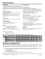
Table 1 -- Close-off pressure ratings of ML6984/7984 Series 4000 with Honeywell valves, psid
Flange
NPT
*Do not exceed 100 psid with valves used in steam applications
ORDERING INFORMATION
When purchasing replacement and modernization products from your wholesaler or distributor, refer to the price sheets for complete
ordering number, or specify— 1. Model number, 2. Valve body type and model number, and 3. Accessories, if desired.
If you have additional questions, need further information, or would like to comment on our products or services, please write or phone:
1. Your local Honeywell Home and Building Control Sales office (Check white pages of your phone directory).
2. Honeywell Customer Care
1885 Douglas Drive North
Minneapolis, Minnesota 55422-4386
In Canada—Honeywell Limited/Honeywell Limitée, 35 Dynamic Drive, Scarborough, Ontario, M1V 4Z9
International Sales Offices in all principal cities of the world. Manufacturing in Australia, Canada, Finland, France, Germany, Japan,
Mexico, Netherlands, Spain, United Kingdom, U.S.A.
95C-10939-4
2
!
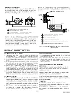
NOTE:


