


GB
8
MU1H-0511GE23 R0720
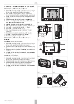
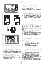
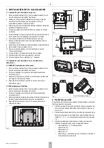
4.13Installation of the Wireless M-Bus module
The Wireless M-Bus module (Fig. 33) is battery-powered and has its own
antenna, so for the purpose of proper operation of the module, just put it in
the appropriate connector.
Note:
Wireless M-Bus modules can be mounted only in the connector marked with number
1 (Fig. 12).
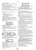
4.14Installation of IMR module (APAT 13x2)
There are three types of IMR modules (Fig. 34): with radio interface (APAT
1312), with radio and cable interface (APAT 1322), with cable interface (APAT
1332).
Modules can be powered, depending on the version, from the calculator or
external power source.
Cable interface (terminal no. 34 and 35) can be used to connect an active
AMPLI antenna – cable order does not matter. For the connection of external
power source (in the range of 4-16 V or stabilised 3.6 VDC) the following
terminals are used: 31 – positive pole, 32 – negative pole.
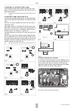
The module supplied by the manufacturer with its own power supply is in the
sleep mode.
The APAT 13x2 module can be activated using the SW1 diagnostic button
(push and hold the button for 5 to 7 seconds, then let go). If APAT 13x2 is a
version without its own power supply or if the system is awake, push and hold
the diagnostic button for 5 seconds to check the operating mode. Correct
operation is signalled with 4x flash of the LED.
Note:
IMR modules can be mounted only in the connector marked with number 1 (Fig. 12).
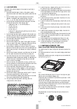
4.15Cable lining inside the calculator
The calculator has been designed to assist you in the installation process as
much as possible. In the base of the device there are special "tunnels" that
help in connection cable lining. The IP54 version of the calculator also
features special pins preventing the cable from being ripped out. In IP65 and
IP68 models this task is performed by cable grommets.
Fig. 35 shows how cable is to be lined inside the device
Fig. 24
Fig. 25
Fig. 26
Fig. 27
Fig. 28
Fig. 29
Fig. 30
Fig. 31
Fig. 32
Fig. 33
Fig. 34
A
B
GDN Vcc
Содержание resideo EW500 Series
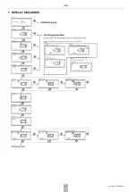
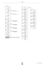
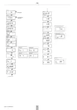
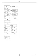
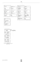
Страница 10: ...GB 10 MU1H 0511GE23 R0720 7 DISPLAY SEQUENCE...
Страница 11: ...GB MU1H 0511GE23 R0720 11...
Страница 12: ...GB 12 MU1H 0511GE23 R0720...
Страница 13: ...GB MU1H 0511GE23 R0720 13...
Страница 14: ...GB 14 MU1H 0511GE23 R0720...
Страница 15: ...GB MU1H 0511GE23 R0720 15...
Страница 16: ...GB 16 MU1H 0511GE23 R0720...
Страница 17: ...GB MU1H 0511GE23 R0720 17...
Страница 18: ...GB 18 MU1H 0511GE23 R0720...
Страница 19: ...GB MU1H 0511GE23 R0720 19...
Страница 20: ...GB 20 MU1H 0511GE23 R0720...
Страница 35: ...PL MU1H 0511GE23 R0720 35...