


GB
MU1H-0511GE23 R0720
5
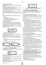
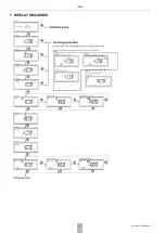
3.1 Numeric value editing
To start editing a numeric value, briefly push the P2 button at the time of its
display (Fig. 11).
The first digit of the edited value will start flashing.
By briefly pushing the P2 button, set the appropriate value; to move to the
next digit editing, briefly push the P1 button (Fig. 11).
To exit the editing mode of a given value, go to the last editable digit and
briefly push the P1 button once more.
As a result, the last digit will stop flashing and the screen will return to the
value display mode, after which it will be possible to select the next value to
edit.
In this way it is possible to configure the following parameters in the
calculator:
•
date and time,
•
network address and customer ID,
•
impulse frequency and serial number for additional inputs,
•
initial value of the meter for additional inputs.
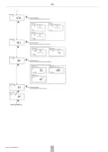
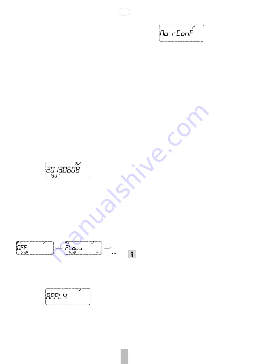
3.2 Date and time editing
Configuration of date and time takes place on the same menu screen.
To edit the date, briefly push the P2 button when in the settings menu.
Editing begins with the year, each next push of the P1 button enables the
editing of the month, day, hour and minutes.
Set date and time are saved in the calculator upon finishing the editing of the
last digit (tens of minutes).
3.3 Additional input type editing
To change the type of the additional input, briefly push the P2 button when
displaying the impulse input type screen.
As a result, the input type will be changed to another type available.
Depending on the input number, it is possible to set the following types of
inputs:
•
inactive input,
•
impulse input with impulse frequency: dm3/imp, imp/dm3, imp/kWh,
•
alarm input,
•
input for digital communication with transducer.
Note:
In case of setting the output type other than an impulse one in the menu, the impulse
frequency and serial number settings for the given input are not displayed.
3.4 Confirmation of the edited parameters
When setting date and time, the parameters in the calculator are updated
immediately after the end of editing.
In order to confirm the remaining values, go to the last screen – confirmation
of configuration group changes.
If there have been changes made to the current configuration, the APPLY
option will appear on the screen.
To save the changed configuration, push and hold the P2 button until the
screen displays "No rConF".
This means that the calculator is already configured in accordance with the
data entered in the configuration menu.
Note:
If the configuration group is abandoned without the implementation of the operation
described above, introduced settings will not be saved in the calculator.
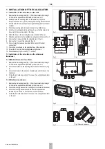
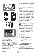
4 ELECTRICAL CONNECTIONS
To make electrical connections, remove the C cover of the calculator (Fig. 5).
The removal method is described in the section "Installation of the
calculator".
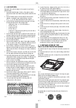
4.1 Connecting the temperature sensors
The calculator can work with two types of temperature sensors (Pt500 and
Pt1000), but for each of them there is a separate design of the main plate of
the calculator.
Temperature measurement can be performed using the Pt500 or Pt1000
sensors, both 2- and 4-wire.
Depending on the number of temperature sensor connection wires, the
calculator connection strips are available in two versions (Fig. 12):
•
calculator with a strip for 2-wire temperature sensor, a strip for the
connection of the main flow transducer and a strip for the connection of
4 additional devices (Fig. 13),
•
calculator with a strip for 4-wire temperature sensor, a strip for the
connection of the main flow transducer and a strip for the connection of
4 additional devices (Fig. 14).
When measuring with 2-wire sensors (Fig. 13), the T1 sensor (power supply
temperature) must be connected to the connector marked with numbers 5, 6,
whereas the T2 sensor (return temperature) – to connector no. 7, 8.
When measuring with 4-wire sensors (Fig. 14), the T1 sensor must be
connected to the connector marked with numbers 5, 6 and 1, 2, whereas the
T2 sensor – to connector no. 7, 8 and 3, 4.
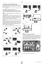
4.2 Connecting the flow transducer
The connection of the main flow transducer is made through a 3-terminal
connector, marked with numbers:
30. power supply output for flow transducer (from the main power source)
31. signal input for the flow transducer
32. signal reference input for the flow transducer
What is more, there is a possibility of connecting the flow transducer
communication cable to the signal input – the fourth additional input (only if
it is configured as a input of digital communication with the transducer).
Fig. 15 shows the method of connecting flow transducers with open collector
output for the transducer requiring power supply from the calculator (1), open
collector output (2) and normally open contact output (3).
In the case of ultrasonic transducers with a 4-wire connection (e.g.
Sharky 473) the fourth wire (yellow) can be connected only if input I4
is configured as a digital communication with the transducer.
Otherwise, do not connect this cable. Incorrect connection may result
in premature battery wear.
Connecting the flow transducer to the NC transmitter
•
connection polarity arbitrary (Fig. 16)
Connecting Sharky 473 ultrasonic transducer (Fig. 17)
Connecting Ultraflow ultrasonic transducer (Fig. 18)
4.3 Connecting the additional flow sensor
The additional flow sensor may be used to detect leaks of the systems
operating in the closed system. It should be connected to the additional input
3. The sensor should be connected with the 2 terminal connector marked
with the following numbers:
54 - signal input for the additional flow sensor,
50 - additional flow sensor signal reference output.
Содержание resideo EW500 Series
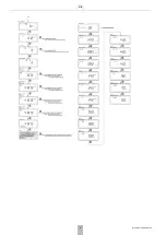
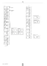
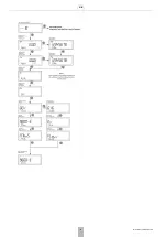
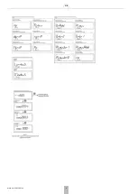
Страница 10: ...GB 10 MU1H 0511GE23 R0720 7 DISPLAY SEQUENCE...
Страница 11: ...GB MU1H 0511GE23 R0720 11...
Страница 12: ...GB 12 MU1H 0511GE23 R0720...
Страница 13: ...GB MU1H 0511GE23 R0720 13...
Страница 14: ...GB 14 MU1H 0511GE23 R0720...
Страница 15: ...GB MU1H 0511GE23 R0720 15...
Страница 16: ...GB 16 MU1H 0511GE23 R0720...
Страница 17: ...GB MU1H 0511GE23 R0720 17...
Страница 18: ...GB 18 MU1H 0511GE23 R0720...
Страница 19: ...GB MU1H 0511GE23 R0720 19...
Страница 20: ...GB 20 MU1H 0511GE23 R0720...
Страница 35: ...PL MU1H 0511GE23 R0720 35...


