


GB
4
MU1H-0511GE23 R0720
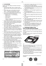
2 LCD SCREEN
Description of the symbols displayed on the calculator screen (Fig.9) is
presented below.
1. Symbol indicating the display of volume or flow value, as well as
additional input values when displayed along with the symbol in the field
no. 2
2. Symbol of additional input or tariff, indicating the display of data
(register or configuration value) for additional input, symbols:
or the values associated with tariffs, symbols: 1, 2.
3. Symbol of instantaneous/minimum/maximum/average or tariff value,
indicating the display of one of the following values:
–
instantaneous value:
for the flow and power,
–
minimum value:
–
maximum value:
–
average value:
–
tariff value
: displayed together with the symbol in the field no.
2, indicating the tariff number.
4. Symbol of power supply temperature, displayed for the instantaneous,
average or peak value, as well as archived power supply temperature
5. Symbol of temperature difference, indicating together with symbols 4
and 6 the display of temperature difference
6. Symbol of return temperature
7. Symbol of cold, displayed for the values of cold registers: energy and
volume, as well as on the screen of temperature difference measured
in time, when the conditions of cold measurement are met
8. Symbol of failure, indicating the occurrence of failure. The symbol is
displayed on the main screen and on the screens associated with that
failure, where in the field no. 18 a message on error type is additionally
displayed
9. Symbol of time, displayed on date and current time screens for the date
and time values associated with archived data and working time
10. Symbol indicating the access level to the configuration of calculator
(displayed on all screens during access unlocking). The blinking symbol
indicates the access to metrological settings, whereas steady light
symbol – access to user settings
11. Symbol of return flow, indicating the flow at variance with the proper
direction. Available only for flow transducers with digital communication
12. Symbol of flow, indicating flow in the proper direction
13. Symbol of low battery, displayed along with the symbols 14 and 15,
indicates the type of low battery (displayed on all screens during the
occurrence of failure) or the type of battery, for which the voltage is
displayed in the service menu
14. Symbol of main battery, displayed along with the symbol 13, indicates
the values or signals the failure of the main battery
15. Symbol of backup battery, displayed along with the symbol 13, indicates
the values or signals the failure of the backup battery
16. The main display field, 8-digit field for displaying values and
configuration data of the calculator
Fig. 9
17. Symbol of the archive, displayed with the symbol 19, 21, 22, 23, 24 or
25, indicates the type of archived data displayed
18. Additional display field, 4-digit field for displaying additional descriptions
of the values displayed in the main field, the error type and the current
or archived time on selected screens
19. Symbol of daily data, indicating the display of archived data from the
daily archive
20. Symbol of optical port activity, appears when the optical port is active
and communication is possible
21. Symbol of monthly data, indicating the display of data from the monthly
archive
22. Symbol of annual data, indicating the display of data from the annual
archive
23. Symbol of hourly data, indicating the display of archived data from the
hourly archive
24. Symbol of minute-based data, indicating the display of data from the
minute-based/configurable archive
25. Symbol of tariff data, indicating the display of data from the tariff archive
26. Decimal symbol, indicating the decimal part of a value or separating
rating different values
27. Decimal separator symbol, highlighting the decimal part of a value
28. Symbol of impulse frequency, indicating the impulse frequency unit
29. Unit field, indicating the unit of value displayed in the main field,
available units of energy, volume, flow, power and time
3 CONFIGURATION OF THE
CALCULATOR FROM THE MENUE
The calculator allows for a manual configuration of selected parameters from
the menu.
You can set parameters such as date, time, network settings and additional
input settings.
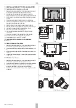
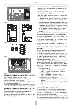
Configuration possibility is secured by a configuration jumper available after
opening the casing (Fig. 10).
Fig. 10
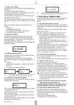
Upon pressing and holding the jumper for 1 second, the configuration group
selection screen is automatically displayed (06).
Configuration group is available for 5 minutes after using the jumper or after
recent activity in this group.
After this time, the display automatically returns from the configuration group
to the main energy; to enable configuration group, use the jumper again.
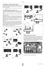
When the possibility of configuration is active, at any time it is possible to exit
and re-enter the group in a standard way.
Upon moving to the configuration menu the current calculator configuration
is read and then displayed during editing.
Navigating between screens of the configuration group takes place in a
standard way.
Fig. 11
,
,
,
,
,
1
2
3
4
5
6
7
8
9
10 11 12 13 14 15
16 17 18
19 20 21 22 23 24 25 26 27 28 29
Configuration jumper
P1
P2
Содержание resideo EW500 Series
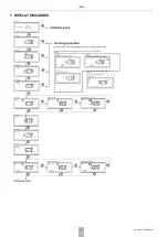
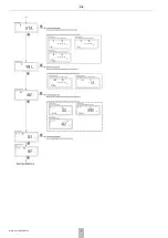
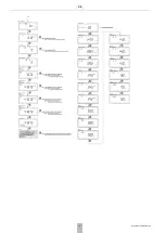
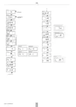
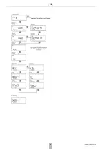
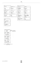
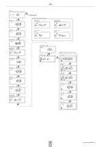
Страница 10: ...GB 10 MU1H 0511GE23 R0720 7 DISPLAY SEQUENCE...
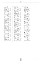
Страница 11: ...GB MU1H 0511GE23 R0720 11...
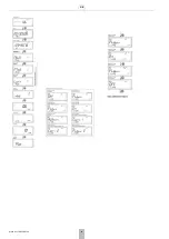
Страница 12: ...GB 12 MU1H 0511GE23 R0720...
Страница 13: ...GB MU1H 0511GE23 R0720 13...
Страница 14: ...GB 14 MU1H 0511GE23 R0720...
Страница 15: ...GB MU1H 0511GE23 R0720 15...
Страница 16: ...GB 16 MU1H 0511GE23 R0720...
Страница 17: ...GB MU1H 0511GE23 R0720 17...
Страница 18: ...GB 18 MU1H 0511GE23 R0720...
Страница 19: ...GB MU1H 0511GE23 R0720 19...
Страница 20: ...GB 20 MU1H 0511GE23 R0720...
Страница 35: ...PL MU1H 0511GE23 R0720 35...


