


E
MU1H-0511GE23 R0720
27
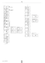
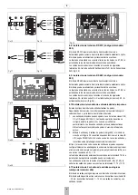
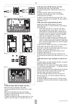
4.15Revestimiento de cables en el interior de el calculador
El calculador ha sido diseñada para ayudarle en el proceso de instalación en
la medida de lo posible. En la base del dispositivo hay "túneles" especiales
que ayudan en el revestimiento de los cables de conexión. La versión IP54
de el calculador también cuenta con clavijas especiales que evitan que el
cable sea arrancado. En los modelos IP65 e IP68 esta tarea se realiza
mediante ojales para cables.
Fig. 35 muestra cómo se debe forrar el cable dentro del dispositivo
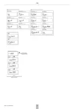
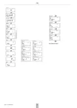
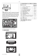
5 DIMENSIONES
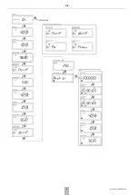
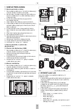
6 DESCRIPCIÓN DEL CÓDIGO DE ERROR
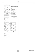
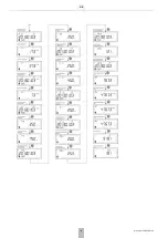
7 SECUENCIA DEL DISPLAY
Fig. 34
159 mm
100 mm
Código Descripción
Tiempo de
respuesta
2
Sin caudal, ΔT diferencial correcta
conf.
4
Error: sensor temp. imp
<10 s
8
Error: sensor temp. ret
<10 s
16
Error: temperatrua diferncial inversa
<10 s
32
Error: (máximo) caudal excedido
<10 s
64
Batería princial baja o sin carga
<10 s/<24 h
128
Bateria backup baja
<24 h
256
Entrada Alarma adicional
<1 s
512
Dirección de flujo incorrecta
<1 mín.
1024
Aire en el flujo
<1 mín.
2048
Sistema de medición del caudalímetro dañado
<1 mín.
4096
Error: no hay comunicación con el sensor de
caudal
<1 mín.
16384 Módulo incorrecto 1
<10 s
32768 Módulo incorrecto 2
<10 s
Содержание resideo EW500 Series
Страница 10: ...GB 10 MU1H 0511GE23 R0720 7 DISPLAY SEQUENCE...
Страница 11: ...GB MU1H 0511GE23 R0720 11...
Страница 12: ...GB 12 MU1H 0511GE23 R0720...
Страница 13: ...GB MU1H 0511GE23 R0720 13...
Страница 14: ...GB 14 MU1H 0511GE23 R0720...
Страница 15: ...GB MU1H 0511GE23 R0720 15...
Страница 16: ...GB 16 MU1H 0511GE23 R0720...
Страница 17: ...GB MU1H 0511GE23 R0720 17...
Страница 18: ...GB 18 MU1H 0511GE23 R0720...
Страница 19: ...GB MU1H 0511GE23 R0720 19...
Страница 20: ...GB 20 MU1H 0511GE23 R0720...
Страница 35: ...PL MU1H 0511GE23 R0720 35...


