Honeywell Home resideo EW500 Series Скачать руководство пользователя страница 13

GB

MU1H-0511GE23 R0720

13

Содержание resideo EW500 Series

Страница 1: ...use Heat Metering Guarde las instrucciones para un posterior uso Medici n de calor Instrukcj nale y zachowa na potrzeby p niejszego u ycia Pomiar ciep a EW5001CD0100 Flow sensor on supply pipe Pt500...

Страница 2: ...ay sequence 10 E 1 Instalaci n de el calculador 21 2 Pantalla LCD 21 3 Configuraci n de el calculador desde el men 22 4 Conexi n el ctrica 23 5 Dimensiones 27 6 Descripci n del c digo de error 27 7 Se...

Страница 3: ...the C cover to the mounting base using B screws 13 Place the seals Fig 6 wire Fig 7 sticker 1 2 Installation of the calculator on the ultrasonic transducer 1 2 1EW400 Ultrasonic Flow Meter 1 Remove t...

Страница 4: ...ith the symbol 13 indicates the values or signals the failure of the backup battery 16 The main display field 8 digit field for displaying values and configuration data of the calculator Fig 9 17 Symb...

Страница 5: ...er of the calculator Fig 5 The removal method is described in the section Installation of the calculator 4 1 Connecting the temperature sensors The calculator can work with two types of temperature se...

Страница 6: ...ower adapter has two sets of terminals marked with numbers 95 and 96 allowing for the supply of power to interchangeable communication modules terminals on modules marked with numbers 97 and 98 The el...

Страница 7: ...is connected through terminals no 97 98 the polarity of the connected power supply is arbitrary The impulse inputs are connected through terminals no 65 66 and 67 68 whereas the signal from the impuls...

Страница 8: ...32 negative pole The module supplied by the manufacturer with its own power supply is in the sleep mode The APAT 13x2 module can be activated using the SW1 diagnostic button push and hold the button...

Страница 9: ...difference error 10 s 32 Maximum flow exceeded error 10 s 64 Low level of main battery or mains power supply failure 10 s 24 h 128 Low level of backup battery 24 h 256 Additional input alarm 1 s 512...

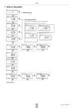
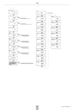
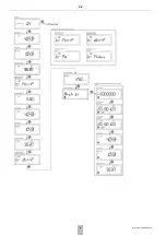
Страница 10: ...GB 10 MU1H 0511GE23 R0720 7 DISPLAY SEQUENCE...

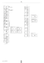
Страница 11: ...GB MU1H 0511GE23 R0720 11...

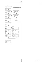
Страница 12: ...GB 12 MU1H 0511GE23 R0720...

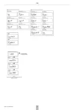
Страница 13: ...GB MU1H 0511GE23 R0720 13...

Страница 14: ...GB 14 MU1H 0511GE23 R0720...

Страница 15: ...GB MU1H 0511GE23 R0720 15...

Страница 16: ...GB 16 MU1H 0511GE23 R0720...

Страница 17: ...GB MU1H 0511GE23 R0720 17...

Страница 18: ...GB 18 MU1H 0511GE23 R0720...

Страница 19: ...GB MU1H 0511GE23 R0720 19...

Страница 20: ...GB 20 MU1H 0511GE23 R0720...

Страница 21: ...ontaje del caudal metro ultras nico Fig 8 3 Desplazar el calculador en direcci n a los orificios para cables hasta que haga clic en el sensor de caudal 4 Seguir las instrucciones en lo punto 8 13 en c...

Страница 22: ...descripciones adicionales de los valores mostrados en el campo principal el tipo de error y la hora actual o archivada en las pantallas seleccionadas 19 S mbolo de los datos diarios que indica la visu...

Страница 23: ...introducidos no se guardar n en el calculador 4 CONEXI N EL CTRICA Para realizar las conexiones el ctricas retire la tapa C de el calculador Fig 5 El m todo de eliminaci n se describe en la secci n In...

Страница 24: ...la fuente de alimentaci n de 230 V y a los terminales marcados con los n meros 27 y 28 Fig 20 Se debe suministrar alimentaci n de 24 V a los terminales marcados con los n meros 97 98 Fig 21 El adaptad...

Страница 25: ...a 1 Las salidas de impulsos pueden operar en una de las tres clases OB OC u OD seg n EN 1434 2 La clase de operaci n de salida se configura durante la producci n y no puede modificarse posteriormente...

Страница 26: ...minal positivo est marcado como Vcc mientras que el polo negativo como GDN Los cables de comunicaci n se conectan mediante un par de terminales situados en la parte superior izquierda del m dulo desig...

Страница 27: ...able dentro del dispositivo 5 DIMENSIONES 6 DESCRIPCI N DEL C DIGO DE ERROR 7 SECUENCIA DEL DISPLAY Ver 7 Display sequence Fig 34 159 mm 100 mm C digo Descripci n Tiempo de respuesta 2 Sin caudal T di...

Страница 28: ...unku otwor w kablowych a do momentu zatrza ni cia si przelicznika na przetworniku 4 Post puje zgodnie z punktami 8 13 opisanymi w przypadku monta u przelicznika na cianie 1 2 2Przetworniki Ultraflow 1...

Страница 29: ...u optycznego symbol wy wietlany w czasie gdy aktywny jest port optyczny i mo liwa jest komunikacja 21 Symboldanychmiesi cznych okre lawy wietlaniedanychzarchiwum miesi cznego 22 Symbol danych rocznych...

Страница 30: ...istnieje osobne wykonanie p ytki g wnej przelicznika Pomiar temperatury mo e by wykonywany za pomoc czujnik w Pt500 b d Pt1000 zar wno 2 jak i 4 przewodowych W zale no ci od ilo ci przewod w przy cze...

Страница 31: ...do zacisk w oznaczonych cyframi 97 98 rys 21 Zasilacz posiada dwie pary zacisk w oznaczonych cyframi 95 i 96 umo liwiaj cych zasilanie wymiennych modu w komunikacyjnych zaciski na modu ach oznaczone...

Страница 32: ...yj cia 2 wej cia impulsowe rys 28 kod modu u 080 wyj cia dla modu u wej wyj maj takie same wykonania jak dla modu u 016 Wej cia mog pracowa w klasie IB lub IC wed ug PN EN 1434 2 W ka dym z przypadk w...

Страница 33: ...rzy rodzaje modu w IMR rys 34 z interfejsem radiowym wyk APAT 1312 z interfejsem radiowym i kablowym wyk APAT 1322 z interfejsem kablowym wyk APAT 1332 Modu y mog by zasilane w zale no ci od wykonania...

Страница 34: ...ka powrotu 10 s 16 B d odwrotnej r nicy temperatur 10 s 32 B d przekroczenia przep ywu maksymalnego 10 s 64 Niski poziom g wnej baterii lub brak zasilania sieciowego 10 s 24 h 128 Niski poziom baterii...

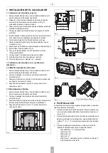
Страница 35: ...PL MU1H 0511GE23 R0720 35...

Страница 36: ...presentative Ademco 1 GmbH MU1H 0511GE23 R0720 Subject to change 2020 Pittway S rl All rights reserved This document contains proprietary information of Pittway S rl and its affiliated companies and i...

Отзывы: