background image


Содержание EZ6500CXS

Страница 1: ......

Страница 2: ...this product Any error or oversight while servicing this this product can result in faulty operation damage to the product or injury to others For Your Safety Because this manual is intended for professional service technician we do not provide warnings about many basic shop safety practices e g Hot parts wear gloves If you have not received shop safety training or do not feel confident about your...

Страница 3: ...nd put on gloves Protect yourself and others whenever you have equipment hoisted in the air Anytime you lift this product with a hoist make sure that the hoist hook is securely attached to the product Make sure the engine is off before you begin any servicing procedures unless the instruction tells you to do otherwise This will help eliminate several potential hazards Carbon monoxide poisoning fro...

Страница 4: ... practical or possible to warn you about all the hazards associated with servicing these products You must use your own good judgement You will find important safety information in a variety of forms including Safety Labels on the product Safety Messages preceded by a safety alert symbol and one of three signal words DANGER WARNING or CAUTION These signal words mean You WILL be KILLED or SERIOUSLY...

Страница 5: ...bricate any sliding surfaces before reassembly After reassembly check all parts for proper installation and operation Many screws used in this machine are self tapping Be aware that cross threading or overtightening these screws will strip the threads and ruin the hole Use only metric tools when servicing this unit Metric bolts nuts and screws are not interchangeable with non metric fasteners The ...

Страница 6: ...14 2 2 FUEL TANK AND STRAINER CLEANING 15 2 3 FUEL TUBE CHECK 16 3 REMOVAL AND INSTALLATION 17 3 1 PREPARATION AND PRECAUTIONS 17 3 2 REMOVAL 19 3 2 1 CONTROL PANEL AND CONTROL BOX 19 3 2 2 FUEL TANK 28 3 2 3 MUFFLER 29 3 2 4 ALTERNATOR 31 3 REMOVAL AND INSTALLATION 33 3 3 INSTALLATION 33 3 3 1 ENGINE AND FRAME 33 3 3 2 ROTOR 33 3 3 3 STATOR 34 3 3 4 BRACKET 2 34 3 3 5 MUFFLER 36 3 3 6 FUEL TANK 3...

Страница 7: ...TE 42 4 3 NO ELECTRICITY AT THE A C RECEPTACLE 43 4 4 ALTERNATING CURRENT VOLTAGE IS 0V 44 4 5 ALTERNATING CURRENT VOLTAGE IS LOW 50 80V 45 4 6 CHECKING STATOR 46 4 7 CHECKING ROTOR 47 4 8 CHECKING BRUSH 48 4 9 CHECKING A V R 49 4 10 CHECKING OTHER ELECTRICAL 50 4 11 WIRING DIAGRAM 51 7 ...

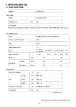
Страница 8: ... rotating type Voltage regulation system AVR Phase Single Rated power factor 1 0 Type R REH RK RA CL M K MK L LB S SB LS Rated Voltage V 220 230 120 220 230 Frequency Hz 50 60 AC output Rated kVA 5 0 5 5 Maximum kVA 5 5 6 5 OTHERS Fuel Tank Capacity ℓ 15 5 Size Length mm 685 690 Width mm 535 670 Height mm 540 610 Continuous operating Hr 5 8 50Hz 5 4 60Hz Dry Weight Kg 80 0 With Wheel kit Specifica...

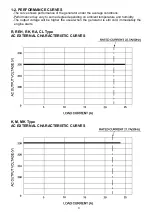
Страница 9: ...ons Performance may vary to some degree depending on ambient temperature and humidity The output voltage will be higher the usual when the generator is still cold immediately the engine starts R REH RK RA CL Type AC EXTERNAL CHARACTERISTIC CURVES K M MK Type AC EXTERNAL CHARACTERISTIC CURVES 9 ...

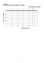
Страница 10: ...L LB Type AC EXTERNAL CHARACTERISTIC CURVES S SB Type AC EXTERNAL CHARACTERISTIC CURVES 10 ...

Страница 11: ...LS Type AC EXTERNAL CHARACTERISTIC CURVES 11 ...

Страница 12: ... A IN TEN A N C E CL EAN EL EMENT EVERY 5 0 HOURS EVERY 1 0 HOURS UNDER DUSTY CONDITIONS WASH IN HIGH F L ASH POINT SOL VENT SQUEEZE DRY THEN DIP IN CL EAN ENGINE OIL AND SQUEEZE OUT EXCESS OIL 1 3 GENERAL DESCRIPTION 12 ...

Страница 13: ... stamped on the label stuck on the fuel tank NOTE Always specify serial number when inquiring about the generator or ordering spare parts in order to get correct parts and accurate service ENGINE SERIAL NUMBER GENERATOR SERIAL NUMBER 13 ...

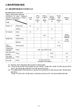
Страница 14: ...lean O Replace O Valve clearance Check Adjust O 2 Combustion Chamber Clean After every 500 Hrs 2 Fuel tank and strainer Clean O 2 2 2 Fuel valve sediment cup Clean O 2 2 2 Fuel tube Check Every 2 years 2 Replace if necessary 2 3 1 Service more frequently when used in dusty areas 2 These items should be serviced by your dealer unless the owner has the proper tools and is mechanically proficient See...

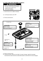
Страница 15: ...e if necessary Clean the fuel valve filter with non flammable solvent and allow them to dry thoroughly OFF Position Fuel valve filter Fuel tank O ring Fuel valve nut 20N m Filter O ring INSTALLATION Before installation clean the screen and check for damage Fuel tank filter Fuel tank cap INSTALLATION Wash to remove the sediment before installing Always wash with gasoline Sediment cup 4 5N m INSTALL...

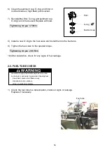
Страница 16: ...ent 7 Reinstall the filter O ring and sediment cup O ring can not be reused Replace with new Tightening torque 4 5 N m 8 Install a new O ring to the fuel valve and install them to the fuel tank 9 Tighten the fuel valve to the special torque Tightening torque 20 0 N m 10 After installation check for any signs of fuel leakage 2 3 FUEL TUBE CHECK 1 Check the fuel tube foe deterioration cracks or sign...

Страница 17: ...eplace them temporarily to their original position 5 Handle disassembled parts with care clean them before reassemble using a neutral cleaning fluid 6 Use all disassembly assembly tools properly and use the proper tool for each specific job TORQUE VALUES Item Thread Dia mm Torque Values N m Remark Fuel valve mount nut 20 0 Sediment cup 4 5 Generator rotor bolt M10 P1 25 45 0 Exhaust pipe mount nut...

Страница 18: ...HOW TO CONNECTION A WIRING To Fuel cut solenoid To Charge coil To Engine switch To Starter motor To Ignition coil ...

Страница 19: ...r 3 Remove the Black wire and White wire from terminal block 4 Remove the Green Yellow wire from bracket 2 Bolt M5 12L 1 5 Cut the wire band Remove the tube Wire band can not be reused Replace with new 6 Remove the cell motor wiring Remove End cover Bolt Wire band Tube Green Yellow wire Black wire White wire Terminal block Bracket 2 Bolt 18 19 ...

Страница 20: ...7 Remove the engine wiring 8 Remove the control panel Bolt M6 25L 4 9 Remove the control box Remove Remove Remove Bolt CONTROL BOX 20 ...

Страница 21: ...nator wiring Connect for the connector To Engine wiring Connect for the Engine terminal To Engine wiring Connect for the Engine terminal Blade fuse midium 5A Fuse 5A Diode Assy Diode COMP Capacitor Assy Green Yellow wire Black wire White wire Engine connecting wire AC OUTPUT SWITCH FUSE VOLT METER PILOT LAMP CIRCUIT BREAKER GROUND TERMINAL Screw M4 16 2 21 ...

Страница 22: ...ct for the bracket To Alternator wiring Connect for the connector Black wire White wire To Alternator wiring Connect for the block terminal To Engine wiring Connect for the Engine terminal To Engine wiring Connect for the Engine terminal Engine connecting wire Green Yellow wire Black wire White wire Capacitor Assy Diode COMP Diode Assy Fuse 5A 22 ...

Страница 23: ...o Alternator wiring Connect for the block terminal Green Yellow wire To Alternator wiring Connect for the bracket Black wire White wire Black wire To Alternator wiring Connect for the connector Engine connection wiring is same to all models Refer to Type R S K or wiring diagram for engine connection wiring Green Yellow wire 23 ...

Страница 24: ...re Engine connection wiring is same to all models Refer to Type R S K or wiring diagram for engine connection wiring Black wire White wire To Alternator wiring Connect for the block terminal Green Yellow wire To Alternator wiring Connect for the bracket White wire To Alternator wiring Connect for the connector Black wire 24 ...

Страница 25: ... is same to all models Refer to Type R S K or wiring diagram for engine connection wiring Green Yellow wire To Alternator wiring Connect for the bracket Black wire White wire To Alternator wiring Connect for the block terminal To Alternator wiring Connect for the connector Black wire White wire Green Yellow wire Black wire 25 ...

Страница 26: ...s same to all models Refer to Type R S K or wiring diagram for engine connection wiring Green Yellow wire To Alternator wiring Connect for the bracket Black wire White wire To Alternator wiring Connect for the block terminal To Alternator wiring Connect for the connector Black wire White wire Green Yellow wire Black wire 26 ...

Страница 27: ...s same to all models Refer to Type R S K or wiring diagram for engine connection wiring Green Yellow wire To Alternator wiring Connect for the bracket Black wire White wire To Alternator wiring Connect for the block terminal To Alternator wiring Connect for the connector Black wire White wire Green Yellow wire Black wire 27 ...

Страница 28: ... OFF Position Fuel tube Fuel valve filter Fuel tank O ring Fuel valve nut 20N m Filter O ring INSTALLATION Before installation clean the screen and check for damage Fuel tank filter Fuel tank cap INSTALLATION Wash to remove the sediment before installing Always wash with gasoline Sediment cup 4 5N m INSTALLATION Check for any leakages after assembly INSTALLATION Before installation clean the scree...

Страница 29: ...th new 3 Remove the exhaust pipe from the engine Nut M8 2 Lock Washer M8 2 CAUTION The muffler becomes very hot during operation and remains hot for a while after stopping the engine Be careful not to touch the muffler while it is hot Allow it to cool before proceeding Bolt Exhaust Pipe Muffler Gasket Bush Pipe Lock Washer M8 Nut M8 Gasket Bolt M8 32L Bolt M8 16L 29 ...

Страница 30: ...4 Remove the Muffler Bracket Bolt M8 16L 1 Bolt M8 25L 1 Bush pipe ALTERNATOR Bush Pipe Muffler Bracket Bolt M8 25L Bolt M8 16L 30 ...

Страница 31: ...the generator set with the bracket 2 upwards 4 Remove the nut fixing bracket 2 onto the mount base with anti vibration rubber Nut M10 2 5 Remove the bracket 1 Bolt M6 165L 4 6 Take out stator cover with crows 2 pcs raised up by using screw driver 7 Remove the stator The stator is heavy Be careful do not hit the coil of the stator to the rotor Disconnect Brush holder AVR Bracket 2 Bolt Bolt Bracket...

Страница 32: ...ng procedures Pour engine oil into the center hole of rotor shaft Fill with oil to the shaft end Size M12 1 75 Apply a few turns of seal tape around the tip of the bolt Use commercially available 0 1mm thick and oil resistant seal tape Screw the bolt into the thread of the rotor shaft Torque the bolt using a socket wrench until the rotor comes off loose The hydraulic pressure inside the rotor shaf...

Страница 33: ...nstall the engine into the frame from the side of it Tighten the nuts over the anti vibration rubber bolts to fix Nut M10 2 Tightening torque 27 0 N m 3 3 2 ROTOR 1 Wipe off oil grease and dust from the tapered portion of engine shaft and matching tapered hole of rotor shaft 2 Mount the rotor to the engine shaft Tighten the Generator rotor bolt Generator rotor bolt M10 275L 1 Tightening torque 45 ...

Страница 34: ...ulling them out from the bracket 2 2 Tap on the rear cover evenly with a plastic hammer to press the rotor bearing into the bracket 2 3 Fix the rear cover with bolts Bolt M6 165L 4 Tightening torque 7 0 N m Tighten the bolts evenly and in turns 4 Install the bracket 2 into the anti vibration rubber Nut M10 2 Tightening torque 27 0 N m Plastic hammer Bolt Bracket 2 Anti vibration rubber Nut Bracket...

Страница 35: ...e slip rings and tighten the brush holder mount bolt If the brush is installed oblique to the slip ring there is possibility that the brush holder can break when the screw is tightened or the brush may break when generator of started Make this process carefully 6 Set stator cover with the crow inserted into slit and bent 2 pcs Insert the bend into the slit and caulking with commercially available ...

Страница 36: ...e from the engine Mount the Exhaust pipe and the gasket on the cylinder head Nut M8 2 Lock Washer M8 2 Bush pipe 2 Gasket can not be reused Replace with new Tightening torque 22 0 N m ALTERNATOR Bush Pipe Muffler Bracket Bolt M8 25L Bolt M8 16L Exhaust Pipe Muffler Gasket Bush Pipe Lock Washer M8 Nut M8 Gasket Bolt M8 32L Bolt M8 16L 36 ...

Страница 37: ...ount the Exhaust pipe and the gasket on the muffler Bolt M8 32L 2 Lock Washer M8 2 Gasket can not be reused Replace with new Tightening torque 22 0 N m 4 Install the Muffler from the muffler bracket Bolt M8 16L 2 Tightening torque 15 0 N m Bolt 37 ...

Страница 38: ...he control panel Bolt M6 25L 4 Tightening torque 7 0 N m 2 Install the wiring from the control panel to the alternator 3 Install the black wire and white wire to terminal block 4 Install the yellow green wire to bracket 2 5 Connect the DC connector to stator connector Bolt Washer Bolt CONTROL BOX Yellow green wire Black wire White wire DC connector Connect Terminal block Bracket 2 38 ...

Страница 39: ... Bolt M5 12L 2 Tightening torque 4 0 N m 7 Connect the cell motor wiring 8 Connect the engine wiring 9 Cover the tube Fix with wire band Wire band can not be reused Replace with new Cover Bracket Connect Connect Connect Connect Wire band Tube 39 ...

Страница 40: ...B LS Rated Voltage V 220 230 120 220 230 Frequency Hz 50 60 Main coil Black White 0 565 0 450 10 Sub coil Yellow Yellow 1 550 1 500 10 Rotor coil 43 10 Ω BRUSH DC WIRING DC COIL BRACKET SUB WIRING SUB COIL EARTH GREEN YELLOW WIRE WHITE WIRE YELLOW WIRE AC TERMINAL BLOCK GREEN WIRE BLACK WIRE WHITE WIRE YELLOW WIRE RED WIRE MAIN WIRING Main COIL WHITE WIRE AVR ...

Страница 41: ...ve ON position Refill the fuel tank Turn the fuel valve to the ON position Turn the switch to the ON position Is there enough oil in the engine Add the recommended oil Is the switch at ON position Please refer trouble shooting of HONDA ENGINE shop manual 4 1 ENGINE DOESN T START 41 ...

Страница 42: ...Check the battery of voltage Check the connect battery Charge the battery Replace the battery Check the fuse Melted of the fuse Check 4 10 OTHER ELECTRICAL Replace the fuse Please refer trouble shooting of HONDA ENGINE shop manual 4 2 ELECTRIC STARTER DOES NOT OPERATE 42 ...

Страница 43: ...NO NO YES Is the AC circuit breaker ON Is the generator working Check 4 1 Engine doesn t start Push to reset theAC circuit breaker is ON 4 3 NO ELECTRICITY AT THE A C RECEPTACLE 43 ...

Страница 44: ...4 4 ALTERNATING CURRENT VOLTAGE IS OV 44 ...

Страница 45: ...Replce the Rotor Is the Brush working Check 4 7 CHECKING BRUSH Replace the brush Is the AVR unit working Check 4 8 CHECKING A V R Is the Stator working Check 4 5 CHECKING STATOR Is the Rotor working Check 4 6 CHECKING ROTOR 4 5 ALTERNATING CURRENT VOLTAGE IS LOW 50 80V 45 ...

Страница 46: ...istance between terminals on stator leads Check here the table Fig 5 1 If stator is faulty replace it with a new one 3 Check the insulation resistance between stator core and each stator lead using a megger tester If insulation is bad replace stator with a new one CIRCUIT TESTER Resistance MEGGER TESTER 46 ...

Страница 47: ...coil windings or when measurement is performed at ambient temperatures different from 20 C 68 F 2 Cleaning Slip rings the slip ring surfaces must be uniformly bright Slip rings showing black spots excessive wear or uneven wear must be repaired A stained slip ring lowers generator efficiency and output voltage Polish the slip rings with fine sandpaper while turning the rotor until rough spots disap...

Страница 48: ...ip rings If not polish smooth the brushes with sandpaper A brush that is not smooth produces arcs between the brush and slip ring leading to possible damage Usable brush lengths are from 7 mm to 11 mm A brush shorter than 7 mm must be replaced because decreased contact pressure between the brush and slip ring lowers generator efficiency and output voltage 7 mm BRUSH 48 ...

Страница 49: ...e A V R or by the inter lead resistance with a tester or actually mounting it in the generator and operating it Replace the case where the resistance is significantly deviated from the measured new one Ω R 20 CIRCUIT TESTER TESTER POLARITY Ω White a Red b Green White Blue Blue TESTER POLARITY Ω White a 2 1M 5 0M 5 1M 4 2M 4 2M Red b 1 8M 2 2M 2 2M 1 9M 1 9M Green 4 6M 2 2M 4 9M 4 7M 4 7M White 4 6...

Страница 50: ...tion Check the position to the pointer of Voltmeter Pointer position 120V 110V to 130V 220V 210V to 230V 230V 220V to 240V Terminal inspection Make sure that the connector does not break the cover Check that the female terminal does not open too much If rusting occurs on the terminals correct with sand paper before connecting Fuse inspection If the over current the fuse will be damage Check visual...

Страница 51: ...4 11 WIRING DIAGRAM R S K Type 51 ...

Страница 52: ...RK LS MK Type 52 ...

Страница 53: ...REH CL Type 53 ...

Страница 54: ...M Type 54 ...

Страница 55: ...SB LB Type 55 ...

Страница 56: ...L Type 56 ...

Страница 57: ...62EAB00 2019 Sep ...

Отзывы: