Carburetor Adjustments & Tuning Tips
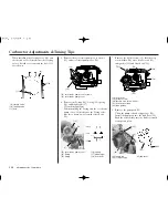
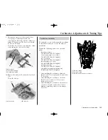
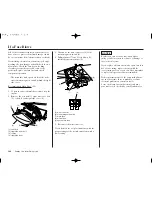
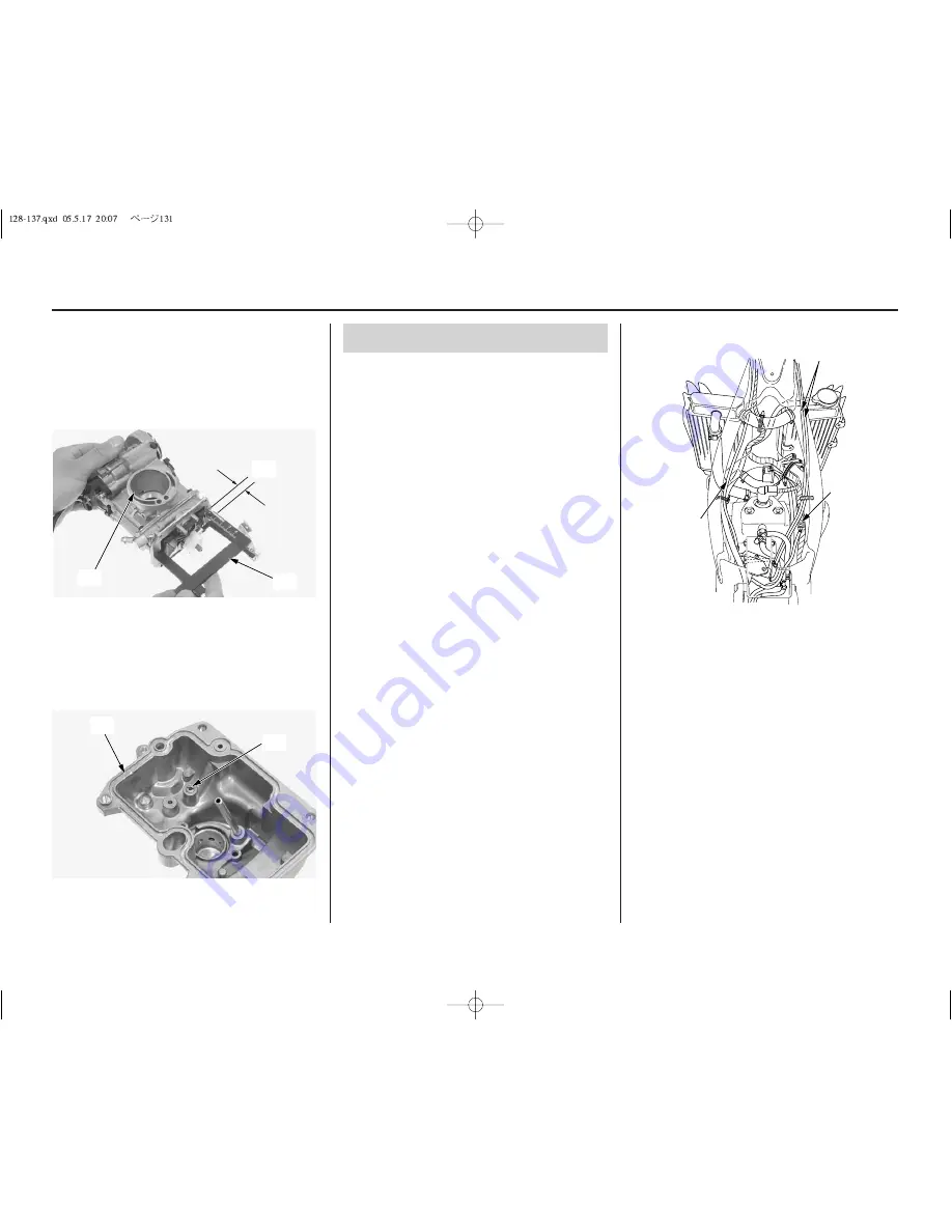
(26) float level
(27) float level gauge
(28) carburetor intake
10.Remove the leak jet (29) from the float bowl
(18).
Clean the leak jet.
9. Measure the float level (26) with the float
level gauge (27) during float tab just
contacting the float valve and the carburetor
intake (28) facing up. The float level should
be 0.31 in (8.0 mm).
If the float level is out of specification, adjust
it by bending the float tab carefully.
(18) float bowl
(29) leak jet
(26)
(27)
(28)
(18)
(29)
Adjustments for Competition
131
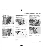
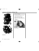
(1) throttle cables
(2) hot start cable
(3) throttle position sensor connector
(2)
(3)
(1)
Carburetor Assembly
To assemble, reverse the disassembly procedures.
To install the carburetor, reverse the removal
procedures.
Tighten the following parts to the specified
torque.
float bowl screws:
1.5 lbf·ft (2.1 N·m, 0.2 kgf·m)
accelerator pump cover screws:
1.5 lbf·ft (2.1 N·m, 0.2 kgf·m)
top cover bolts:
1.5 lbf·ft (2.1 N·m, 0.2 kgf·m)
throttle drum cover bolt:
2.5 lbf·ft (3.4 N·m, 0.3 kgf·m)
hot start cable nut:
1.5 lbf·ft (2.1 N·m, 0.2 kgf·m)
shock absorber upper mounting nut:
32 lbf·ft (44 N·m, 4.5 kgf·m)
• After installing the carburetor, adjust the
throttle cable (1) free play and hot start cable
(2) free play.
• After installing the carburetor, check the
throttle sensor connector (3) for correct
routing as necessary.
• After installing the carburetor, check the air
vent hoses (4) and overflow hose (5) for
kinking or pinching and correct routing as
necessary.
Содержание CRF250X 2006
Страница 1: ...2006 Honda CRF250X OWNER S MANUAL COMPETITION HANDBOOK ...
Страница 10: ...6 Motorcycle Safety ...
Страница 16: ...12 Before Riding ...
Страница 26: ...22 Basic Operating Instructions ...
Страница 150: ...146 Taking Care of Unexpected ...
Страница 165: ...Technical Information 161 Wiring Diagram ...
Страница 166: ...162 Technical Information ...
Страница 177: ...Memo 173 ...
Страница 178: ...174 Memo ...
Страница 179: ...Memo 175 ...

