HSK_operating_manual_English_Ver3.doc
HOMA Pump Technology
-
34
Wiring diagram examples
Страница 1: ...ual_English_Ver3 doc HOMA Pump Technology 0 Operating manual HOMA Pump control HSK15 25 Please follow safety guidelines in chapter 2 Version 03 0 06_300704 SW Version 1 10c HW Version 1 00 Date 21 10 2004 Библиотека СОК ...
Страница 2: ...ays 9 5 1 Main menu 9 5 2 Main display 10 5 3 Pump operation mode 11 5 3 1 Change of pump operation mode using menus 11 5 3 2 Change of operation mode additional keys 12 5 3 3 Change of operation mode by means of external switches 12 5 4 System menus and settings 12 5 5 Messages after starting the system 13 6 System menus 14 6 1 Level measurement 14 6 1 1 Level measurement setting 14 6 1 2 Zero ad...
Страница 3: ...ternal Off 28 8 3 External alarm 29 9 Fault messages 29 10 Standard settings 31 11 Setting and wiring guidelines 31 11 1 Pumps without a second thermo contact 31 11 2 Pumps with PTC 32 11 3 Operation with rechargeable batteries 32 11 4 Level sensor and float switch connection 33 11 5 Level measurement according to the impact pressure method 35 11 6 Voltage surge protection 35 12 Appendix 35 12 1 E...
Страница 4: ...atures of the HSK25 pump control 2 Safety guidelines This operating manual exclusively describes the control unit section It contains important references and warnings and therefore should be read by the installer as well as by the relevant operator before installing and operating the unit Note Not only should the general safety references mentioned in this Safety guidelines section be observed bu...
Страница 5: ... electrical board are to be observed The OFF position of the internal switches is not be used in order to carry out maintenance of the pump s For this purpose the main switch shall be used The integrated manual motor starter can also be used switch to 0 position and secure properly against renewed switching for example by means of a padlock If the fuse of the control1 is faulty it should only be r...
Страница 6: ...g shall be observed 3 1 Main switch When the control is equipped with a main switch then the control is switched on or off by means of the main switch The enclosure cover can only be opened when the main switch is in the OFF position The main switch has an emergency off function and it stops the pump s The master switch can be locked in the OFF position by means of a padlock Remark If the control ...
Страница 7: ...surement methods 1 External level sensor measuring range from 0 1m WC up to 0 10m WC adjustable 4 20mA interface additionally a float switch PSN as high water level monitor 2 Internal impact pressure measuring sensor measuring range 0 2 m WC for connection to a wet bell using a pneumatic tube additionally a float switch PSN as high water level monitor 3 Up to 4 float switches PSN 4 2 Pump control ...
Страница 8: ...ated Note Run time monitoring also takes place in case of high water 4 2 5 Special characteristics when operating two pumps When operating two pumps two different operation modes are to be distinguished Alternating or rotation operation 1 1 Peak load operation 2 When operating the control with two pumps the pumps will operate on a rotation basis that is the pumps start alternatively so that on an ...
Страница 9: ...l as the polarity of the relay contacts are programmable Using the internal terminal block the relays can optionally be supplied with either 230V control voltage or with the internal 12V DC voltage 4 4 Operation and Displays For display purposes the control unit features a two line LCD Display 16 digits The displays appear in clear text in the selected country s language English French Italian Dut...
Страница 10: ...lays and operation steps necessary for normal function are carried out and shown and in System Menus by means of which the control is parameterised Each menu consists of a sequence of images in the LCD Display Scrolling from display to display is effected by means of arrow keys 5 1 Main menu The following diagram shows the menu structure of the control Using the arrow keys you can scroll up and do...
Страница 11: ...he different variants of indication are more precisely explained as follows Single pump operation P1 IA 5 7A 074cm Dual pump operation P1 IA 5 7A 074cm P2 0M 0 0A Pump P1 is running I in automatic operation mode A current draw 5 7 A level 74 cm Pump P2 is switched off 0 in manual operation mode M current input 0 0 A Operation with one float switch P1 IA 5 7A 0 P1 0M 0 0A Operation with two floats ...
Страница 12: ... details on the fault indication see Chapter 6 other indications After the control unit has finished its initialisation in the lower right hand corner a flashing triangle will indicate that the unit is using mains supply or by a flashing battery symbol in case the rechargeable battery is being used 5 3 Pump operation mode The operation mode for each pump can be changed between the operation modes ...
Страница 13: ...is no fault present If in a two pump operation mode one pump is switched to OFF the control continues to function as a single pump control if the other pump is in the AUTOMATIC operation mode 5 3 3 Change of operation mode by means of external switches By means of toggle switches fixed to the housing cover the operation mode of the pump can be switched between operation modes AUTOMATIC manual ON a...
Страница 14: ...password is requested Password Using the arrow keys a respective position within the password can be changed Using the OK key the next position up to the fourth position can be selected If the valid password has been entered in future the adjustment values can be directly changed The factory default password is 0000 If the wrong password has been entered the message false password appears Promptin...
Страница 15: ...nt 4 20mA 0250cm Automatic Zero Adjustment Filter 0 9999 0000 Minimum Pressure 0005cm back to Main Menu 6 1 1 Level measurement setting In this menu the level measurement method is determined After pressing the OK key the level measurement method can be selected by means of the or key Following possibilities are available level measurement 4 20mA interface through level sensor measuring range adju...
Страница 16: ...led out of the water A working level sensor is to be connected If the internal impact pressure sensor is used for measuring the wet bell must be pulled out of water Furthermore it must be guaranteed that the measurement system is absolutely still during the zero calibration process After preparations in this menu point zero adjustment the OK key must be pressed select YES using the or keys and con...
Страница 17: ... the OK key on the lower right the sign appears Now with the arrow keys the value of the highest digit can be changed Using the OK key the next position is selected etc When entering the last digit is effected on the lower left a sign may possibly appear instead of the sign This means that the selected setpoints are inconsistent for example a cut out level is higher than a cut in level When the da...
Страница 18: ...ump runs uninterruptedly longer than the set time period an alarm is given In case of a dual pump control rotation of the pumps is additionally effected A value of 0000 deactivates this function 6 2 3 Pump rotation when using dual pump control In this menu point the behaviour of the control concerning pump rotation can be determined When entering a value of 0000 pump rotation is effected only afte...
Страница 19: ...pump must be set If the current exceeds the rated value an alarm is given after a certain time period The more the current exceeds the rated value the shorter this time period is before an alarm is given If the measured current falls below half the value of the rated current then an under current alarm is given5 In order to ensure a safe function the entered value should be approx 10 that of the c...
Страница 20: ...her an automatic reset is enabled for the fault Alarm Auto reset mask respectively Therefore in all four mask words must be determined In the control each fault in a 32 bit binary number is allocated one bit If the fault occurs then this bit is set 1 otherwise its value is 0 When a fault event is now to be signalised for example by alarm relay 1 then in the mask this bit must also be set to 1 If t...
Страница 21: ...ump1 are to be activated then all bits of the groups 8 7 6 must be 0000 0HEX The bits of groups 3 4 must be 1111 FHEX and those of group 5 must be 0111 7HEX the bits of the groups 1and 2 must be again 0000 0HEX Therefore the fault mask is 0007FF00 If for example only the faults aux1 and aux2 for each pump and the external faults are not to be used then in groups 5 and 8 the resulting value is 0001...
Страница 22: ...Conversion of group bits into a hexadecimal digit 6 4 1 Alarm Auto Reset In this menu the behaviour of the CPSm in case of faults can be adjusted Here two settings for each fault case are possible AUTOMATIC reset mask bit 0 or MANUAL reset mask bit 1 In the AUTOMATIC position the fault indication is reset and the control continues to operate when the fault is not present any longer In the MAN posi...
Страница 23: ...flashing NO flashing This function can be individually selected for each relay This function is important in order to determine the behaviour of the controller in case of an alarm due to mains voltage loss You can determine whether the alarm relay should remain in the alarm position or not In this state the relay is deactivated in any case the NO relay contact is open the NC contact is closed When...
Страница 24: ...switched off after exceeding the set number of T1 alarms until the reset button has been pressed only when The T1 fault in the Alarm Auto Reset mask has been set to 0 automatic reset The nxT1 fault in the Alarm Auto Reset mask has been set to 1 manual reset have been entered 6 4 7 High water alarm delay If the high water level is exceeded or after the high water float switch trips a delay time per...
Страница 25: ... the number of pumps 1 2 1 1 can be selected by means of the or key Following options are available 1 one pump 1 1 alternating operation two pumps 2 peak load operation two pumps Selection is confirm with the OK key 6 5 4 Time delay start After switching on the controller the controller will not start immediately The controller is activated only after the set delay time has elapsed In case of a ma...
Страница 26: ...hed A value of 000 deactivates this function Note This function eventually demands that by means of the run on time the shaft has been thus far emptied that the wet bell is hanging free not under water 6 5 7 Date time and SW Version10 Here date the current time as well as the actual software version are displayed for example Date Time V1 10 21 05 99 14 45 The colon in the indication flashes in sec...
Страница 27: ...yes must be entered and confirmed When No is selected then the counters are not deleted 6 6 4 Supply and rechargeable battery voltage In this menu the rechargeable ACC and the internal control voltage PW are displayed In the second line a control value EC followed by the word POWER indicates whether the controller is supplied by the mains plug symbol or by the rechargeable battery battery symbol E...
Страница 28: ... of 1 pump cut out level of 2 pump cut in of 1 pump cut in level of 2 pump alarm level If during operation a higher level is measured than the alarm level then a high water alarm is given The following tables show the switching behavior of a dual pump control in peak load operation a single pump control and a dual pump control in alternating operation under continuous level measurement and during ...
Страница 29: ...ated by either a change in level or by a change in the float switch state the pump does not switch off immediately but only after the set run on time elapses 8 Special functions 8 1 AUX inputs Independently of the control each pump can be switched off by an AUX input In normal operation the input must be bridged If the input is open then the corresponding pump is stopped and an AUX1 fault is recog...
Страница 30: ...elow the minimum value During level measurement using the internal impact pressure sensor the alarm is released when the pressure falls below the minimum value 4 3P Phase sequence phase loss Mains or phase sequence fault This fault occurs when phase connection to the controller has been carried out incorrectly or when there is a loss of at least one of the phases 5 Accu Rechargeable battery voltag...
Страница 31: ...rmo contact of the pump has tripped n amount of times The pump will be switched off This fault should be reset on the control panel 23 P2T2 Thermal contact 2 of pump 2 has tripped The second thermo contact of pump 1 has tripped The pump is switched off This fault should confirmed on the controller This fault is also saved to memory after power loss and is 0 voltage safe 24 P2MS Motor protection of...
Страница 32: ...o reset mask 04604640 Short time run every 48h Mask Relay 1 7FFFFFFF Short time run period 3 sec Mask Relay 2 0007FF00 Forced emptying every 24h Mask Relay 3 7FF00000 Maximum run time 0 sec HW delay high water Alarm 0 sec Password 0000 Grey background not available for HSK15 Language German 11 Setting and wiring guidelines 11 1 Pumps without a second thermo contact Some pumps feature only one ther...
Страница 33: ...operating time however could be significantly shorter In case of control voltage loss first the fault message POWER is generated and the control continues to operate When the rechargeable battery voltage falls below approx 10 5 V then additionally the fault message ACCU is generated At this point of time all relays are deactivated in order to keep the load on the rechargeable battery as low as pos...
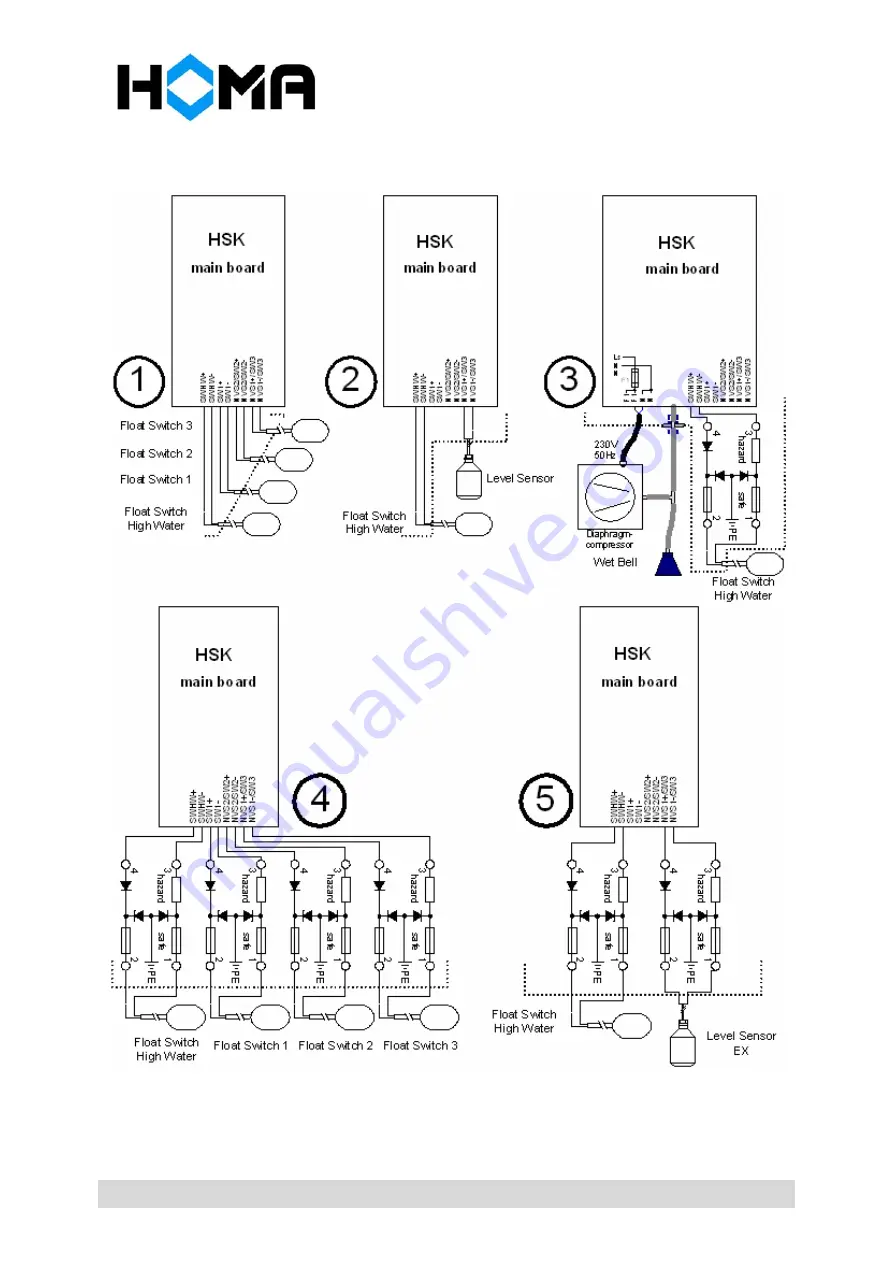
Страница 34: ... the cable from the terminal of the battery Caution the removed terminal should not touch any other conductive parts Attention Protect the battery pack against deep discharge Short circuit of the battery shall be prevented at all times 11 4 Level sensor and float switch connection When the control is operated with an internal level sensor then it has to be connected to the connections of level 1 A...
Страница 35: ...HSK_operating_manual_English_Ver3 doc HOMA Pump Technology 34 Wiring diagram examples ...
Страница 36: ...he pump at the 0cm level can be used however to monitor the function of the small air compressor Using the additional run on time the system is adjusted in such way that the wet bell is outside the water The pressure or the measured level respectively can not be zero Otherwise the pump or the small air compressor is faulty Monitoring of the minimum pressure checks if the pressure falls below the a...
Страница 37: ...ranges depending on the type Thermal over current and magnetic short circuit trip or thermal overload relay Fault current protection option 4 pole RCD rated fault current 30mA Required back up fuse maximum 3 x 25A G for control with direct start other depending on pump switching capacity Level sensor output 4 20 mA two wire Supply voltage of level sensor Typically 24V DC Measuring accuracy input o...
Страница 38: ...2 x M25 10 18mm 1 x M25 8 14mm 5 6 x M16 4 8mm 1 x M12 3 6mm Pressure connection tube 8mm outer 6mm inner 12 3 Wiring and connecting diagrams Wiring and connecting diagrams depend on the existing features of the control and are not a part of this manual They are enclosed separately The layout of the wiring terminals X2 of the control board shows the following picture HSK25 above HSK15 below On the...
Страница 39: ...ling please open the cover and screw the control to the wall or to the mounting plate tightly with the four screws Dimension of the mounting holes for the control units up to 200 x 400mm see diagram on the left After installation carry out the required electrical wiring Close the cover and screw tight Attention In order to comply to the Degree of Protection IP54 the enclosure cover must be closed ...