background image


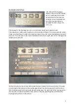
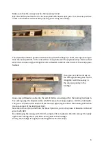
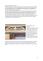
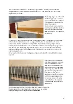
As shown in Fig. 3, we use a roller 
for gluing R9 and R10. This allows 
the  glue  to  be  applied  in  an 
evenly thin layer. Press the parts 
together for several hours. 


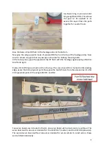
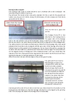
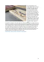
Glue the balsa strips R8 flush to the fuselage sides at the bottom.  
Now glue the wing supports made of plywood R6 flush on the top of the fuselage sides. Take 
care to remove any glue that may escape in the slots for holding the wing bolts. 
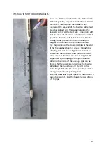
In the canopy area, glue the plywood strip R7 flush with the fuselage, again paying attention 
to left and right. 
 
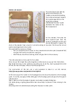
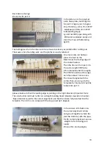
Frames R1 to R5 have a small notch on the top. The servo board R3 is marked on the leading 
edge, as are the 4mm plywood parts. Now glue the two M5 nuts from the accessories into the 
4mm plywood parts of the wing bolts R11 and R12. 


Two servo boards are included in the kit, one servo board with cutouts and one without. The 
servo board with cutouts is intended for the HEPF H47 (rudder) and the KST X06 (elevator). 
The second servo board without cutouts is intended for servos similar in construction, these 
can be fitted individually. 

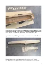
Part R25 behind the 

motor bulkhead  

Содержание Purito

Страница 1: ...described in the assembly instructions When building the model observe all safety regulations for handling tools and adhesives We use thick and thin superglue for assembling the model unless otherwise specified Particular care must be taken to ensure that the components are properly glued You can also find a very good build log at https www rcgroups com forums showthread php 3656529 PURITO 21 New ...

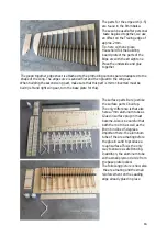
Страница 2: ... to R10 make sure that there is a left and a right part each since the motor bulkhead is glued with side pull The side pull in the motor bulkhead shortens the right side of the fuselage and lengthens the left side On the 2nd picture you can see all the parts that are needed for the construction The parts are arranged in the picture as they will be assembled The 0 6mm plywood reinforcement R10 is a...

Страница 3: ...d strip R7 flush with the fuselage again paying attention to left and right Frames R1 to R5 have a small notch on the top The servo board R3 is marked on the leading edge as are the 4mm plywood parts Now glue the two M5 nuts from the accessories into the 4mm plywood parts of the wing bolts R11 and R12 Two servo boards are included in the kit one servo board with cutouts and one without The servo b...

Страница 4: ... same way the parts of the wing bolts R11 and R12 are only inserted into the slots provided for them but not glued yet Now the hull boat can be taken out of the slipway and inserted with the bottom side facing upwards This is followed by the lower fuselage planking We start with part R13 which is glued to the front of the fuselage at the motor bulkhead Important here part R13 is slightly beveled o...

Страница 5: ...5 see picture The parts R25 R27 are there to fit the fuselage to the spinner later On the top of the fuselage glue the balsa part R17 between the canopy opening and the engine bulkhead here the wood grain runs crosswise Be careful here part R17 is again beveled on one side due to the engine side pull Glue the two symmetrical plywood parts R19 into the canopy R18 in the holes provided ...

Страница 6: ...he fuselage planking R22 and fit it together with the canopy in the canopy opening in the fuselage Glue a piece of Bowden cable into the slot of R20 as a counterpart for the locking mechanism Tip when gluing the Bowden cable into R20 place the canopy approx 0 3mm underneath The goal is to position the bottom of the canopy slightly higher above the building board than the counterpart of the latch p...

Страница 7: ...rbon rods all parallel on a wooden board and fix them with a weight Then the hull boom can be aligned exactly at 90 degrees to the individual carbon rods You should take the necessary time here because the clean alignment of the carbon rods for the tail unit has a significant influence on the flight behavior of the model When the carbon rods are correctly aligned they can be glued in place The pyl...

Страница 8: ...e remaining struts and glue them in the same way The same procedure is to be used for the rudder Here too we first staple the outline together and then work our way up from the bottom Tip harden the holes in the rudder to accept the pins To do this insert a greased 2mm drill bit into the hole and apply a drop of liquid super glue to it The construction of the tail unit is also explained in detail ...

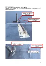
Страница 9: ...uselage boat The wing support is checked once again for protrusions to ensure a flat support surface for the wing center section Rudder and elevator 90 degrees Elevator and auxiliary rail parallel Insert R5 and fix it with a clamp Support 1cm before the end of the pipe ...

Страница 10: ...all parts can be aligned parallel to the drawn line The fuselage tube lies neatly in the holder the fuselage lies flat in the fuselage slipway The elevator lies parallel to our screwed on auxiliary rail The fuselage side panels are pressed to frame R5 with clamps Before gluing check again for correct alignment The fuselage must lie without tension in its slipway and end support Only a correctly al...

Страница 11: ... at this first 45 phases These phases are easier on consistency too control and help us maintain a uniform radius When the desired hull shape has been created all wooden parts are made with a finer sandpaper approx 240 grit sanded again to make it smoother Surface For grinding the A tip in advance We glue a sandpaper over the entire length of the Tail unit on a wooden slat Then the Tail as seen in...

Страница 12: ...ire edge curve When smoothing the rounding ismake sure that there is actually a curve at the end A pointed oneThe leading edge of the tail unit would have a negative impact on flight characteristics At the end all that is missing is the bevel for the rudder deflection Located by the elevatorthe bevel on the underside of the rudder at the rudder on the left side where the rudder horn will later be ...

Страница 13: ...agnets on the inside of the trunk tube fixed Tip the position of the Bowden cables at the end of the The fuselage boom is already through the cut outs given In the fuselage it is important to ensure that the Bowden cables match the used servos are executed You can now use approx 15 drops more liquid Superglue along the Bowden cable into the inside of the fuselage pipe can be dripped So the supergl...

Страница 14: ... part C to the cut to length CFRP tube 7mm diameter 262mm length The CFRP should be at the edge arch Pipe about 7mm survive The ribs will aligned with the combs Then you can go to the Template for the feet of the Ribs tucked into part C please make sure that the leading edge is pointing in the right direction Important here The construction aid must lie flat on a straight building board ideally sc...

Страница 15: ...it is removed from the base and the back 5mm soaked with liquid superglue and then do not sand The trailing edge should only be carefully sanded off once more after soaking so that you don t take away too much material We recommend one here at the end Thickness of 1mm If you now turn to the second trailing edge make sure that a left and right trailing edge is required With the end strips wing part...

Страница 16: ...wing part make sure that this part is mirror inverted must be built left and right wing ear turn the base plate for this The surface parts B are just like the surface parts C built up The only difference is that also here a 7mm aluminum tube as Glued in surface plug in must become Also is be careful that both the root rib as well as the End rib inclined 5 degrees Important here the aluminum tube o...

Страница 17: ...ddle with the ribs A1 2mm plywood These are placed on the CFRP pipe that has been cut to length 12mm diameter 695mm length threaded This is followed by the remaining ribs of the Designation according to All ribs are inserted into the A25 together with the two end ribs Stencil inserted Tip take enough Time for so many Ribs these too clean with the combs on the Align the base plate The End ribs A25 ...

Страница 18: ...ibs can be at a 90 degree angle to the Spar to be aligned We weight down the ribs with weights so that they are completely in the To press base plate Now we start to press in the leading edge at the root rib A25 Rib by rib the leading edge is now threaded towards the middle Tip approx 15 ribs are threaded on the leading edge can be glued to the root rib That makes things easier thread Then the two...

Страница 19: ...hat for Middle part from the base plate and place it under the feet of the leading edge with 2mm and at the trailing edge with 8mm below Then glue the trailing edge to sash part A The component A2V is located on the 8mm balsa board and is placed under the plywood part A1V glued and engraved flush Tip a drill with the Diameter of 5mm throught he balsa blocks A2V at Glue stuck so that the Holes exac...

Страница 20: ... become The flap is in the Wings inlaid The magnets can now on the bottom of the component KF3 placed be come Align the magnets by itself now Consequently can also the rest Magnet from the Glued underside of the wing become The magnetic Attraction is therefore int his version already There is enough Should Should our solution be for the Flap opening used will become one Servo arm extension require...

Страница 21: ... These pieces come with a Slightly sharpened sandpaper and in the surface center part plugged Now can do that too Ear can be put on but with a small one Gap to the root rib Tip we put a 2mm balsa between the middle part and the ear and fix it in place together with two brackets The bottom of the ear can now be cleaned be aligned to the middle part Whether the two parts are exactly aligned with one...

Страница 22: ...us the Significantly negatively affect the flight characteristics of the model We recommend ORACOVER light foils for covering the Puritos When the model is completely covered the GRP control horns are still in the for it to glue the cutouts provided The longer rudder horn is for the Elevator the shorter one used for the rudder The linkages are in the to attach outer holes of the rudder horns so th...

Отзывы: