background image

18

XL-LG20004UM-en-US Rev B · 2018-09-17 · Amendments and Errors Reserved · © SAF-HOLLAND, Inc., SAF-HOLLAND, HOLLAND, SAF, 

and logos are trademarks of SAF-HOLLAND S.A., SAF-HOLLAND GmbH, and SAF-HOLLAND, Inc.

Troubleshooting

9.  Troubleshooting

PROBLEM

POSSIBLE CAUSE

RESOLUTION

Hard to Crank  
Landing Gear

Turning the crank in the 
wrong direction

Refer to “Landing Gear Operation” for proper crank rotation. 

Attempting to raise or lower 
trailer in high gear.

Shift into low gear. DO NOT ATTEMPT TO LIFT OR LOWER IN HIGH GEAR

.

 Doing so could result in damage 

to the landing gear. 

Cross shaft binding.

Inspect cross shaft bolts. Back off bolts to allow lateral (side to side) movement of the cross shaft. 
Straighten or shorten cross shaft to eliminate binding.

Misaligned landing gear legs. Legs MUST be parallel and extend and retract evenly. Remove cross driveshaft and adjust landing gear legs 

to same height.

Lack of grease.

Grease landing gear legs as provided in the “Lubrication” section.

Damaged lift screw or nut.

Check landing gear for signs of impact (accident) damage. Disconnect cross shaft and crank legs individu-
ally to determine which leg is damaged. Replace entire retract assembly or damaged leg.

Interference between powder 
metal bushing or jackshaft of 
gearbox and trailer mounting 
surface.


Trailer mounting surface may need to be modified to ensure no interference between bushing or jackshaft 
and trailer surface.

Upper housing or retract tube 
may be bent.

Replace damaged part(s) or landing gear.

Excessive wear or damage  
to pinion, bevel, input, idler 
and/or output gears.

Replace damaged gears.

Bearing boss is pushed inside 
housing.

Replace jackshaft and O-ring with jackshaft repair kit designed for landing gear models sold after January 2013.

Weld blow through where 
strut bracket is welded to 
housing.

Grind weld as required and re-weld. (With no-load on landing gear, the retract tube should have free play 
inside the housing.)

Hard to crank landing 
gear under load only.

Damaged collar.

Replace the collar

Damaged thrust bearing.

Replace the thrust bearing.

Crankshaft jams or 
skips while turning.

 Inner leg screw damaged.

Examine the lift nut and screw of the inner leg assembly for impact (accident) damage. Replace  
components or leg as necessary.

Worn, broken, or damaged 
gears (missing teeth).

Examine pinion, bevel pinion and all gearbox gears for missing teeth or other signs of damage or wear. 
Replace components as necessary.

Landing gear will NOT 
shift between gears.

Low input gear is frozen or 
binding on the shift shaft.

Follow procedures in the Troubleshooting Guide XL-LG11424TS-en-US to restore easy shifting.

Gearbox leg operates 
but opposite leg 
DOES NOT.

Broken/damaged cross  
driveshaft bolt.

Replace cross driveshaft bolt.

Broken/damaged cross 
driveshaft.

Replace cross driveshaft.

Bevel gear pin/pinion gear pin 
sheared in non-gearbox leg.

Remove upper leg cover. Check for damaged or missing pins under bevel gear, or in pinion gear and  
replace as necessary.

Bevel gear/pinion gear  
damaged in non-gearbox leg.

Remove upper leg cover. Check for damaged gears and replace as necessary.

Non-gearbox leg 
operates, but gearbox 
leg DOES NOT.

Bevel gear pin/pinion gear pin 
sheared in gearbox leg.

Remove upper leg cover. Check for damaged or missing pins under bevel gear, or in pinion gear and  
replace as necessary.

Bevel gear/pinion gear  
damaged in gearbox leg.

Remove upper leg cover. Check for damaged gears and replace as necessary.

Both legs will NOT 
operate, shift shaft 
will turn but output 
shaft DOES NOT turn.

Damaged input, idler, and/or 
output gear.

Remove gearbox cover. Inspect and replace broken gears.

Gear pin(s) sheared in gearbox. Remove gearbox cover. Inspect and replace broken pins.

Both legs will NOT 
operate, but shift 
shaft and output 
shaft turn.

Bevel gear pin/pinion gear pin 
sheared in both legs.

Remove upper leg covers. Check for damaged or missing pins under bevel gear, or in pinion gear and 
replace as necessary.

Bevel gear/pinion gear  
damaged in both legs.

Remove upper leg covers. Check for damaged gears and replace as necessary.

Legs locked and will 
NOT turn

Bent retracting screw or  
damaged riser nut and screw.

Check landing gear for signs of impact (accident) damage. Disconnect cross shaft and attempt to crank legs 
individually to determine which leg is damaged. Replace entire retract assembly or damaged leg.

Содержание Atlas 55

Страница 1: ...Atlas 55 Atlas 65 and Atlas iM Installation Operation and Maintenance Manual XL LG20004UM en US Rev B...

Страница 2: ...s NOTE Includes additional information to enable accurate and easy performance of procedures IMPORTANT Includes additional information that if not followed could lead to hindered product performance U...

Страница 3: ...The alerts provide information that can help prevent serious personal injury damage to components or both Failure to follow the instructions and safety precautions in this manual could result in impr...

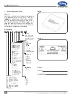
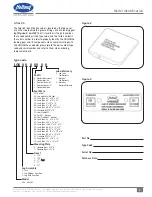
Страница 4: ...Univ Mt 53 Holes B Conv Mt 53 Holes H I Beam Mt 53 Holes L Reverse Mt 53 Holes Travel 1 Special 3 13 50 5 15 50 7 17 9 19 Shafts 0 Universal 1 Reverse 2 I Beam 6 5 8 Special 9 Conventional A I Beam 1...

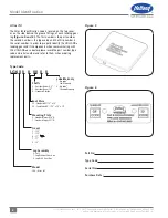
Страница 5: ...Date Mounting Plate 0 Standard Taper 656 1 Standard Taper 531 Shafts 0 Standard Universal 1 Standard Inside 2 Outside I Beam 6 5 3 Outside I Beam 10 4 Standard Outside Lube Warranty 0 Std Lube Std War...

Страница 6: ...al number In order to properly identify the HOLLAND landing gear and its components when communicating with SAF HOLLAND or a dealer please record the part number type code and serial number and refer...

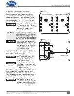
Страница 7: ...n the jack shaft bushings jack shaft shift shaft and the trailer frame could cause hard cranking and wear which if not avoided could result in minor moderate injury or component damage Before installa...

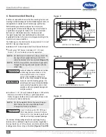
Страница 8: ...brackets to penetrate through the housing and make contact with the retract tube Failure to follow the installation instructions and bracing recommendations in this manual could create a crush hazard...

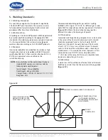
Страница 9: ...han the thinnest material being welded Figure 12 LACK OF FUSION OF ANY KIND IN THIS AREA IS NOT ACCEPTABLE AT ANY TIME PENETRATION AS MEASURED THROUGH SEAM TARGET PENETRATION TO BE OF THINNEST MATERIA...

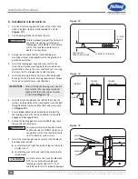
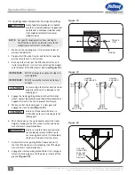
Страница 10: ...urer s specifications IMPORTANT After installing the bracing use a square to ensure that the legs have remained aligned with the trailer and each other as illustrated Figure 14 6 Install the crank han...

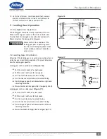
Страница 11: ...ld result in death or serious injury 7 2 Landing Gear Orientation Determine if the landing gear is an outside conventional or an inside reverse mount before operation The mount determines how the land...

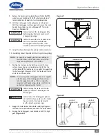
Страница 12: ...e completed IMPORTANT DO NOT couple the tractor and trailer at an angle Failure to align the tractor and the trailer properly could result in damage to the landing gear 4 Engage the tractor parking br...

Страница 13: ...pecific uncoupling instructions relating to the fifth wheel tractor and trailer refer to the respective manufacturer s instructions 1 Position the tractor and the trailer on a well lit level surface c...

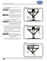
Страница 14: ...anger Figure 25 Failure to secure the crank handle in low gear when NOT in use could allow unplanned landing gear operation which if not avoided could result in property damage 6 Per the manufacturer...

Страница 15: ...ed prior to operation to avoid damage and possible injury Failure to check the condition of landing gear prior to operating could result in use of damaged product which if not avoided could result in...

Страница 16: ...r other signs of damage 3 Repair or replace any broken or damaged part of the landing gear assembly or mounting structure Failure to repair or replace damaged landing gear components can result in uns...

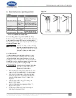
Страница 17: ...e the landing gear legs are in alignment with the trailer and parallel with each other using a square Figure 28 Bent or damaged legs are an indication of possible damage to the lift screw lift nut or...

Страница 18: ...ams or skips while turning Inner leg screw damaged Examine the lift nut and screw of the inner leg assembly for impact accident damage Replace components or leg as necessary Worn broken or damaged gea...

Страница 19: ...19 XL LG20004UM en US Rev B 2018 09 17 Amendments and Errors Reserved SAF HOLLAND Inc SAF HOLLAND HOLLAND SAF and logos are trademarks of SAF HOLLAND S A SAF HOLLAND GmbH and SAF HOLLAND Inc Notes...

Страница 20: ...l component assembly SAF HOLLAND Original Parts are tested and designed to provide maximum performance and durability Will fits look alikes or worse yet counterfeit parts will only limit the performan...

Отзывы: