


11
Adres producenta/ Adresse des Herstellers/ Manufacturer’s Address/ Адрес производителя
GTV Poland Sp. z o.o. Sp. k., ul. Przejazdowa 21, 05-800 Pruszków
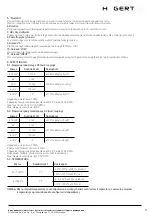
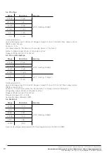
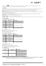
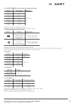
5-7. Diode and continuity
Range
Description
Note
An approximate
forward drop in volta-
ge will be displayed
The voltage in an open
circuit is about 1.5 V.
Built-in buzzer
sounds when the
resistance is less
than about 30 Ω
The voltage in an open
circuit is about 0.5 V.
Overload protection: 250 V DC / AC RMS Continuity test: when the resistance is 50 Ω to 100 Ω,
the buzzer may or may not sound. When the resistance is greater than 100 Ω, the buzzer will not sound.
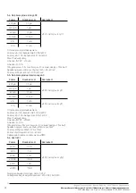
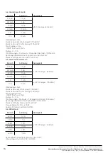
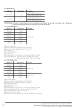
5-8. Capacity
Range
Resolution
Accuracy
40 nF
10 pF
±(8% r 10 digits)
400 nF
100 pF
±(5% r 5 digits)
4 uF
1 nF
40 uF
10 nF
100 uF-2 mF
100 nF
5-10. Frequency
Range
Accuracy
5/50/500/5K
±(1.0% r 3 digits)
50K/500K/5MHz
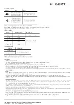
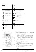
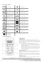
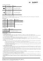
6. MEASUREMENTS
6-1. V voltage measurement
1) Connect the black lead to the COM socket and the red lead to INPUT socket.
2) Set the function switch to the V or V . Select automatic range or manual range with the „RANGE” button.
3) In the manual range, if the measured voltage is not known in advance, select the highest range.
4) Connect test leads to the source or measured circuit.
5) Read the result on the screen. The polarity of the red lead connection will be indicated during the DC measurement.
Note:
a. In a small range, the meter may display an unstable reading when the test leads are not connected to the circuit being measured.
This is normal and will not affect measurements.
b. In manual range mode, when the meter shows the „OL” overrange symbol, select a higher range.
c. To avoid damage to the meter, do not measure a voltage exceeding 600 V for DC) or 600 V for AC).
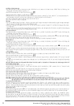
6-2. Current measurement
1) Connect the black lead to the COM socket. If the measured current is less than 200 mA, connect the red lead to INPUT socket.
If the current is between 200 mA and 10 A, connect the red lead to 10 A socket.
2) Set the range switch to the needed µA, mA or A range.
If the measured current is not known in advance, set the range switch to the highest range position and then decrease until a satis-
factory resolution is obtained.
3) Select the DC or AC measurement with the Select button.
4) Select automatic range or manual range with the „Range” button. In the manual range, if the measured current value is not known
before, select the highest range.
5) Connect the test leads in series with the circuit being measured.
6) Read the reading on the display. In the case of direct current measurement, the polarity of the red lead connection will also be
given.
Note: When the „OL” overrange symbol appears in the display, select a higher range.
6-3. Resistance measurement
1) Connect the black lead to the COM socket and the red lead to INPUT socket (Note: The polarity of the red lead is positive „+”).
2) Set the range switch to „
”
3) Set the Select button to the range „
”
4) Select automatic range or manual range with the „Range” button. In the manual range, if the measured current value is not known
before, select the highest range.
5) Connect test leads to the measured circuit.


