background image

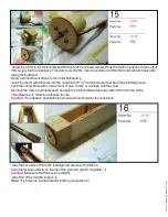
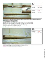
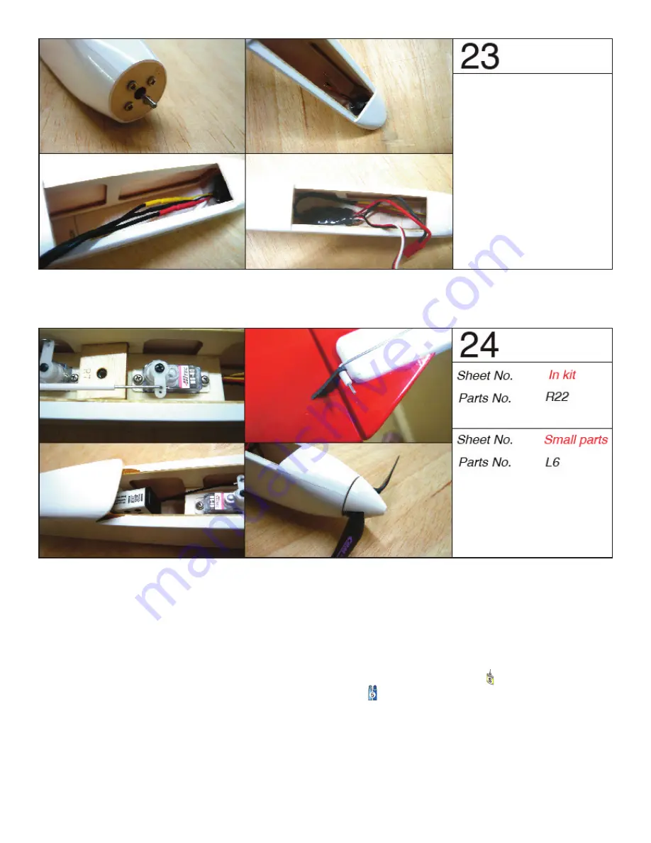
• Install the motor and the ESC.

Note

: To prevent the motor cable rubbing between the motor bell and the fuselage. Glue in a small piece of balsa 

over the wires to the fuselage doubler.

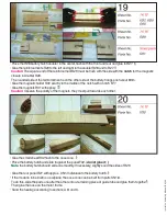
• Install the servos (no screws yet). Set servo arms accordingly.

• Create Z bend on the pushrod R22 at one end and install on the servo arm.

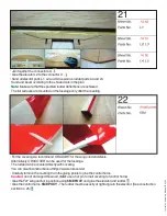
• Insert (do not glue, see below

**

) the rudder horn L6 into the slot provided for the rudders. 

• Insert the pushrod into the guide tubes and connect the servo arms at center.

Attach servos with screws.

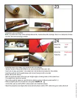
• Bend the pushrod cables at the rear end at right angles and hang them on the rudder horn.

The rudder must also be at neutral.

• Secure the pushrod cables on control horn by sliding a piece of leftover guide tube R21.

**

When everything fits, the control horns are glued. 

5M EPOXY

• Connect the servos and the ESC to the receiver and install the receiver.

• Mount the propeller according to their enclosed instructions and GO FLY (after doing your safety checks)!!

In

no

va

tio

As

se

m

bl

M

an

ua

l (

EN

) V

9

Содержание Innovation

Страница 1: ...d all be allowed to fully cure and be secured with needles or weights Construction The temperature and humidity of the plan can lead to dimensional differences to the components The adhesives given in this manual are only suggestions For large area gluing a thick liquid adhesive is suitable To do this apply the adhesive to the component and then float and align Do not worry the component can still...

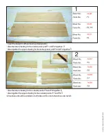
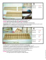
Страница 2: ...lue together the upper sheeting for the center panel part F3 and F4 together Glue the lower sheeting for the outside panels F5 and F6 together Glue together the upper sheeting for the outside panels F7 and F8 All surfaces should be sanded on both sides until no more transitions can be felt Innovation Assembly Manual EN V9 ...

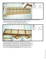
Страница 3: ...he goal is to have the trailing edge at 0 5mm thick The plywood ribs F11 should be glued to the middle rib F12 on both sides Glue together F27 wing anchorage Wing anchorage will be glued AFTER covering Assemble and glue ribs F13 at their given positions on the sheeting F1 F2 and on the web spar F9 Glue the center rib F11 F12 and the reinforcement F12a at the specified position Line up the hole in ...

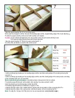
Страница 4: ...ing edge F22 into the recesses of the ribs for the center panel If the leading edge lines up well with the ribs and the sheeting then glue in place Insert the leading edge F23 into the recesses of the ribs for the outer surface parts If the leading edge lines up well with the ribs and the sheeting then glue in place Plane or sand the leading edge following the profile See also section D and E Whil...

Страница 5: ... the center part using the stencil S14 Cut the overhanging sheeting on the leading edge and the sand the leading edge of the outer panels according to the templates S15 S17 S19 and S21 Note on positioning the templates template number corresponds to the rib number The leading edge F22 should not be visible after sanding See also section D and E Sand the sheeting at the trailing edge follow the air...

Страница 6: ...connection rib F14 with a knife Dry fit the wing joiner F26 to the center panel with the arrows to the outside and verify the V shape Measure 55 3mm on the rib F21 The connecting ribs should be flush to each other If everything fits glue both wing joiners F26 with the arrows to the outside on the center panel Use 5M EPOXY Warning The gluing surfaces for the spar and the sheeting must be flat flush...

Страница 7: ...omponent for the construction of the fuselage Glue the fuselage doubler R3 exactly flush to the side part R1 R2 Glue the lower doubler R4 to the bottom edge exactly flush with the side part R1 R2 Glue the upper doubler R5 at the top edge exactly flush to the side part R1 R2 Note When using white glue allow all components to complete cure Secure the needles and or weights Spend the time now to be p...

Страница 8: ...all fit at right angles into the corresponding slots of the doubler R3 of the right fuselage Glue to right side Note For R6 the notch for the wing anchor points upwards see sectionA In the case of the frame R11 the holes are pointing upwards see section B Mark the installation location for the R12 bulkhead Glue R13 in position Glue the left side of the fuselage Use weights or small clamps Keep eve...

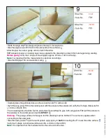
Страница 9: ...roove Tack the components with small amount of glue Clamp or use tape until they cure Remove the motor and tape paper and glue the motor bulkhead securely with a thin CAto the entire circumference Allow the adhesive to cure Caution The adhesive penetrates the wood grain and hardens the nose block Glue the nose block R14 to the fuselage and secure with clamps Align the fuselage directly on the top ...

Страница 10: ...ion of the pushrod cables R22 If necessary slightly enlarge the openings in the sides of the fuse using a 2mm drill bit File opening at angle to fit tube Secure the guide tubes with epoxy After curing cut the guide tubes flush with the sides Note The guide tubes run crosswise behind R12 Glue the rear fuselage cover R23 to R26 starting from the frame R11 Caution Be careful to not twist the boom whi...

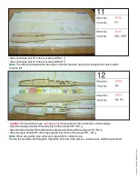
Страница 11: ...nets R31 with epoxy Caution Observe the polarity of the magnets they must pull towards each other Glue the small sheet R32 flush to the nose cone Place the battery hatch and slide it against the panel F32 do not glue it Note the battery hatch should slide on smoothly If necessary slightly sand the sides of R29 Glue the rear panel R27 with approx 0 5mm distance to the battery hatch If the model is ...

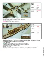
Страница 12: ...e wings and stabilizers Alternatively ORACOVER can be used for the fuselage The rudder can be covered directly with covering You can also find instructions at https www oracover de Carefully remove the covering from the gluing points to glue the control horns Caution do not damaged the wood hint use a hot pin to melt covering for control horns Glue the F27 wing anchor in position using 5M EPOXY an...

Страница 13: ...he rudders Insert the pushrod into the guide tubes and connect the servo arms at center Attach servos with screws Bend the pushrod cables at the rear end at right angles and hang them on the rudder horn The rudder must also be at neutral Secure the pushrod cables on control horn by sliding a piece of leftover guide tube R21 When everything fits the control horns are glued 5M EPOXY Connect the serv...

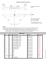
Страница 14: ...ty o N 1 Lower sheeting center Balsa 1 5mm 74 02 F1 1 Lower sheeting center Balsa 1 5mm 74 03 F2 1 Upper sheeting center Balsa 1 5mm 74 03 F4 2 Lower sheeting outer Balsa 1 5mm 74 07 2 Lower sheeting outer Balsa 1 5mm 74 05 m m 0 2 a s l a B Rib 0 1 74 08 m m 0 2 a s l a B Rib 2 74 08 F5 m m 0 2 a s l a B Rib 2 set 74 09 F6 F7 F8 F13 F14 F14 F21 1 Upper sheeting center Balsa 1 5mm 74 01 F3 2 Upper...

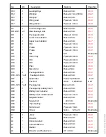
Страница 15: ...9 R30 R31 R32 R33 Frame 74 18 Small parts 3 M Nut o tray v r e S 74 19 Rib 74 19 Rib 74 19 m m 5 2 a s l a B Nose block 1 74 21 In kit m m 0 0 5 x 8 0 Steel Pushrod Fuselage top Balsa 2 0mm 74 12 Balsa 3 0mm Balsa 3 0mm Balsa 3 0mm Balsa 3 0mm Elevator Horizontal stab Vertical stab Fin Rudder 74 12 Small parts 74 12 74 18 74 18 74 15 R34 L1 L3 L4 L5 Joiner L2 Small parts 0 2 x 3 M Nylon Screw 1 74...

Страница 16: ...on of adults To build the model While building the model follow all safety regulations when handling tools and adhesives Observe the safety instructions in the assembly instructions Only use adhesives or similar adhesives specified by the manufacturer which have the same properties Use the installation components specified by the manufacturer or those specified with same technical data Follow the ...

Отзывы: