background image

13

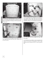
ESC AND BATTERY POSITION

The ESC position is laterally in the fuselage, to have enough 
space for the battery. Use an anti-slip pad below the battery 
to keep it stable in position. The battery can be fi xed with two 
Flitework battery belts (300mm).

GET THE MODEL READY TO FLY

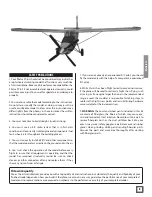
CHECK THE CONTROL DIRECTIONS


1. Turn on the transmitter and receiver and center the 

trims. If necessary, remove the servo arms from the servos and 
reposition them so they are centered. Reinstall the screws that 
hold on the servo arms.


2. With the transmitter and receiver still on, check all the 

control surfaces to see if they are centered. If necessary, adjust 
the clevises on the pushrods to center the control surfaces.

FULL

THROTTLE

RUDDER

GOES

RIGHT

ELEVATOR 

GOES DOWN

LEFT AILERON

GOES DOWN

RIGHT AILERON

GOES UP

4 CHANNELS SETUP

(STANDARD MODE 1)

FULL

THROTTLE

RUDDER

GOES

RIGHT

ELEVATOR 

GOES DOWN

LEFT AILERON

GOES DOWN

RIGHT AILERON

GOES UP

4 CHANNELS SETUP

(STANDARD MODE 2)


3. Make certain that the control surfaces and the carburetor 

respond in the correct direction as shown in the diagram. If any 
of the controls respond in the wrong direction, use the servo 
reversing in the transmitter to reverse the servos connected to 
those controls. Be certain the control surfaces have remained 
centered. Adjust if necessary.

ENGLISH

Содержание FLWA4100

Страница 1: ...manual to the model 78179 Distributed by www hobbico de Technical data Pilatus PC6 L Wingspan 2200 mm Length 1740 mm Take off weight 5500 g Wing Area 86 6 dm Wing load 63 5 g dm Motor set FW 5065 330...

Страница 2: ...Content of delivery 6 Part List 6 Assembling the main gear 7 Tail wheel assembly 7 Installing the 5065 engine 8 Elevator assembly 9 Installation of the rudder 10 Installing the towing clutch 11 Gluein...

Страница 3: ...d components fuel tank wheels etc throughout the building process 5 You must correctly install all R C and other components so that the model operates correctly on the ground and in the air 6 You must...

Страница 4: ...quired to build the Pilatus PC6 L Great Planes Pro CA and Epoxy glue are recommended 1 2 oz Thin Pro CA GPMR6001 1 2 oz Medium Pro CA GPMR6007 6 Minute Epoxy GPMR6045 30 Minute Epoxy GPMR6047 Small T...

Страница 5: ...ing FLWA4106 Pilatus PC 6 2200mm canopy FLWA4107 Pilatus PC 6 2200mm landing gear FLWA4108 Pilatus PC 6 2200mm wing struts FLWA4109 Pilatus PC 6 2200mm wing joiner FLWA4816 Pilatus PC 6 2200mm accesso...

Страница 6: ...e 1x Tail gear 2x Main wheels 100mm 1x Tail wheels 1x Set of vakuum molded windows 1x Left wing with flaps 1x Right wing with flaps 1x Carbon fibre wing joiner 800 x 16 mm 1x Carbon fibre wing joiner...

Страница 7: ...ts from the upper side Nowyoucaninstallthesuspensionstrutintohubandfuselage Use big shims on the outer side 3 Fix the suspension strut with shims and M4 internal thread bolts together with the threade...

Страница 8: ...drilling in the center of the marks 3 Screw the 38mm bolts with M4x20 screws to the firewall using 20x4mm shims on both sides of the firewall frame Thread lock blue Drill a 10mm hole on the lower sid...

Страница 9: ...ting in flight direction If the servos meet together in the middle of the fuselage take distance plates to get them free If you are using a S BUS system like Futaba dont forget to note the servo IDs b...

Страница 10: ...you can use a key file to widen the slots a little bit Glue the hinges first into the flap Afterward glue the flap into the rudder Take care that the rudder flap is very good movable 2 Test the positi...

Страница 11: ...In open position the steel wire should be complete out of the clutch opening This is necessary that the towing rope can be released easily GLUEING THE PLASTIC PANES 1 Cut out the plastic panes along...

Страница 12: ...90 degrees INSTALLATION OF THE LANDING FLAPS All levers with 3 holes on the bottom are for the main wing All lever with 2 holes on the bottom are for landing flaps 1 All levers should be glued to win...

Страница 13: ...check all the control surfaces to see if they are centered If necessary adjust the clevises on the pushrods to center the control surfaces FULL THROTTLE RUDDER GOES RIGHT ELEVATOR GOES DOWN LEFT AILE...

Страница 14: ...tached If required tail weight may be added by cutting open the bottom of the fuse and gluing it permanently inside Note Do not rely upon the adhesive on the back of the lead weight to permanently hol...

Страница 15: ...s are secure the prop is secure and all pushrods and connectors are secure Also check the landing gear after every flight RANGE CHECK Ground check the operational range of your radio before the first...

Страница 16: ...n freely 7 Make sure all hinges are securely glued in place 8 Reinforce holes for wood screws with thin CA where appropriate servo mounting screws cowl mounting screws etc 9 Confirm that all controls...

Отзывы: