


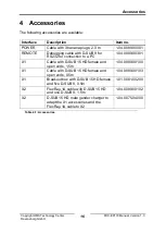


Connections
Copyright HMS Technology Center
Ravensburg GmbH
9
FRC-EP170 Manual, Version 1.3
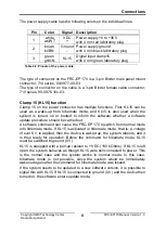
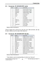
Pin
Signal
Description
1
+5 V
+5 V power supply for remote control,
maximum current 20 mA
2
REM1 / TX
REMOTE1 digital output
RS232 TX transmission signal to PC
3
REM2 / RX
REMOTE2 digital output
RS232 RX received signal from PC
4
REM3
REMOTE3 digital output
5
WKUP
Wake-up option through remote
6
GND
7
-
Not used
Table 2-4: Pinouts of the REMOTE connector
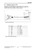
The type of connector on the FRC-EP 170 is a 7-pin Binder female panel
mount connector, 710 series, 09-9478-00-07.
The type of connector on the cable is a 7-pin Binder male cable connector,
710 series, 99-9475-10x-07.
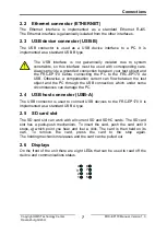
The back of the device is equipped with the following connectors:
Figure 2-4: Back of the FRC-EP170
The connectors are provides as DSUB HD15 (High Density 15-polig).
Содержание FRC-EP170
Страница 1: ...Hardware Manual FRC EP170 Automotive Platform ...
Страница 22: ......


