


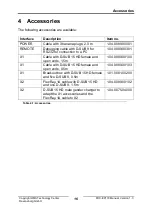


Connections
Copyright HMS Technology Center
Ravensburg GmbH
11
FRC-EP170 Manual, Version 1.3
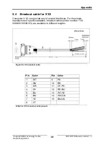
2.10 Connector X1/2 Signal Details
2.10.1 FlexRay
The FRC-EP170 provides a FlexRay interface with two independent FlexRay
communication controllers. Both controllers work on a shared FlexRay bus that
is divided into channels A and B. However, via software they can be switched
to work on individual FlexRay buses. In this case two times the channel A is
brought to the connector. There is no bus termination resistor integrated into
the device. If a bus termination resistor is required, it must be connected to the
cable and/or to the connector. Always use suitable measurement leads for the
device.
The device is also available as a CANonly variant. In that case the
FlexRay controllers are built in but deactivated by software.
2.10.2 CAN Hi/Lo-Speed
For ISO 11898-2 high-speed CAN there are no bus termination resistances
integrated into the device. If a bus termination resistance is required, it must
be connected to the cable and/or to the connector. Suitable CAN
measurement lines are available from IXXAT as accessories.
The ISO 11898-3 low-speed CAN coupling is connected through two
integrated termination resistors of 2 kOhms each (RTH, RTL).
2.10.3 LIN
The interfaces can be used either as masters or slaves. In master mode,
a 1 kOhm resistor is used on VBAT for LIN. In slave mode, this resistor is not
connected.
2.10.4 K-LINE
For the K-Line interface, there is only one "K" line available. The interfaces can
be
used
either
as
masters
or
slaves.
In
master
mode,
a 1 kOhm resistor is used on VBAT for K-Line. In slave mode, this resistor is
not connected.
2.10.5 Digital I/O
The direction of the digital I/O’s can be selected by software.
When used as digital output, a maximum level of 5V is reached when switched
on. The output level voltage is dependent on the load. At the maximum load of
20mA a voltage level of 2.4V is reached (TTL High-Level). A protection for
long lasting shortcuts or connections higher voltages is not implemented.
When used as input, the voltage level for detecting a logical ‘1’ is typically
2,4V. The inputs are implemented by using Schmitt-Triggers, i.e. threshold for
the level transition is provided.
The actual status of a digital output can be read back by the corresponding
input.
Содержание FRC-EP170
Страница 1: ...Hardware Manual FRC EP170 Automotive Platform ...
Страница 22: ......


