Doc.Id. SCM-1200-080
Anybus X-gateway CANopen - PROFIBUS
Doc.Rev. 1.02
Appendix D
D. CANopen Configuration Example
D.1 Configuration Example
This section includes an example of how to configure the CANopen network interface of the Anybus
X-gateway CANopen using the CANopen Configuration Manager from PORT
1
. Other configuration
tools are available and can of course be used instead. The module is configured as a master in the exam-
ple.
By default the module is configured as a CANopen slave with 16 byte input and 16 byte output data,
that can be transferred between the CANopen network and the PROFIBUS network. To configure the
module as master and change the input and output data sizes, follow the steps below.
Step 1. Baud Rate and Node Address
Baud rate and node address are set using the rotary switches on the side of the module, see “Configura-
tion Switches” on page 14.
Step 2. Set Module in Master Mode
To change to master mode, bit 0 in CANopen object 1F80h (see “NMT Start-up, 1F80h” on page 34)
has to be set and saved during CANopen configuration. Using the CANopen Configurator from PORT,
this is done as follows:
1.
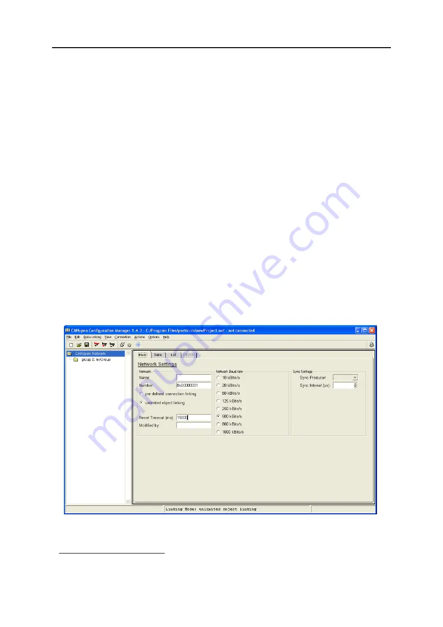
Open program and select network info. Set the baud rate to match the baud rate set by the con-
figuration switches on the module. Set Sync Interval (if used). Set Reset Timeout to the longest reset
time for any node in hte network.
1. Available for download at www.anybus.com. This version can only be used for products from HMS Industrial Networks.


