25 (36)
►
Click button
Next
.
→
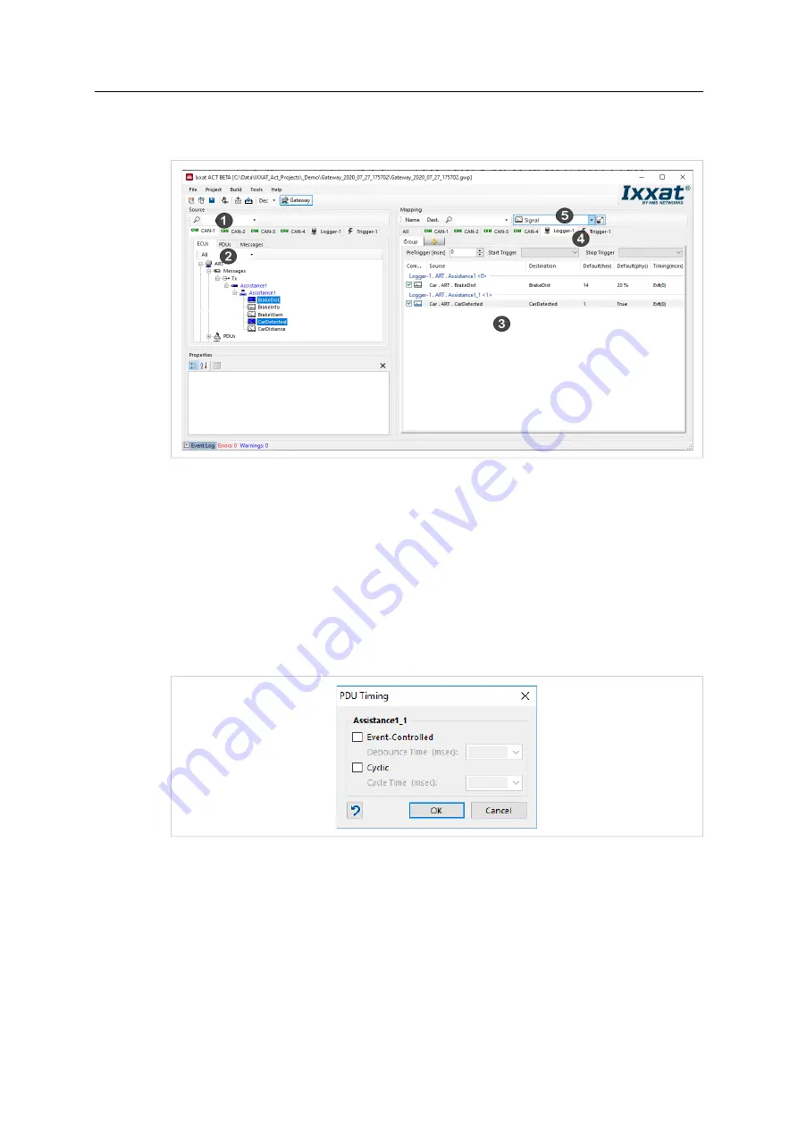
Window to configure the logger is opened.
Fig. 25
Logger configuration window
►
Select the desired CAN bus as source (
1
) and the tab
Logger
(
4
) as destination.
►
In source open tab
ECUs
(
2
).
►
In drop-down list
Map Subject
select
Signal
(
5
)
►
To log individual signals, drag and drop the data to be logged from source (
2
) to destination
logger (
3
).
→
By default, signals are logged event triggered: when a signal is received, the signal is
logged.
►
To log a signal only in defined intervals, right-click the mapped signal on logger destination
(
3
) and select
Timing
.
Fig. 26
Defining interval
►
To log the signal in defined cycles, select
Cyclic
and define the cycle time.
►
To define a debouncing time for a signal (next signal is only logged if the defined time is
exceeded), select
Event-Controlled
and define the debounce time.
►
An individual interval can be selected for each mapped signal.
►
If desired use signals as trigger (see
Using Signals as Trigger, p. 26
).
►
When the logger configuration is finished, open menu
Build
and select
Build
to produce the
logger configuration.
CANnector Log User Manual
4.01.0091.21000 1.1 en-US


