background image


10

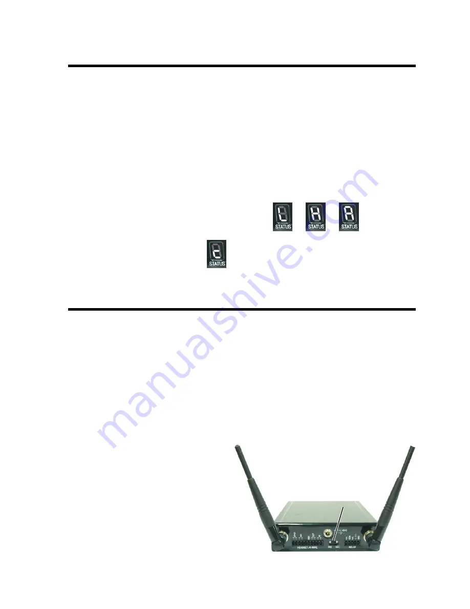
Rear panel of Base Station 

PRI  SEC 

switch 

Interference Avoidance 

Interference, which may be heard in a headset as popping sounds, may occur whenever other equipment such as 
WI-FI systems, wireless DMX systems, other HME Base Stations, etc. use the same frequency band.  If these 
systems can be limited to one portion of the band, then the DX121 can be set to the opposite half of the 2.4 GHz 
to 2.48 GHz band.  To avoid this type of interference, set up the base stations for “split-band” operation by 
selecting the upper part of the frequency range on one Base Station (or more), and the lower part of the 
frequency range on the other(s) as follows: 


Turn on the Base Station power.  An “

8

” will appear on the 

STATUS

 display for a few seconds. 


After the “

8

” disappears and the 

STATUS

 display is blank, press and hold the 

CLR/BND

 button and then, 

while you are still holding the 

CLR/BND

 button, press and hold the 

REG

 button and wait until a 

L

H

 or 

A


appears, and then release both buttons. 


Press the 

CLR/BND

 button to cycle through parts of the  

frequency band; 

L

 = Low end, 

H

 = High end and 

A

 = All. 

Stop on the band that you want to select. 


Wait until “

c

” appears on the display.     


NOTE:


Base stations are shipped in the 

A

 (default) position. 


Multiple Base Station Setup 

This mode of operation can be used to expand the number of users communicating through multiple HME Base 
Stations operating in the same portion of the 2.4 GHz to 2.48 GHz frequency band. 

Primary and Secondary Base Station Settings 

One Base Station must be designated as “Primary” while the others are designated as “Secondary”.  You 
can have only one primary and up to 3 secondary Base Stations.  Secondary Base Stations are assigned 
numbers 1, 2, or 3.   


Label the Base Stations as “Primary,” “1,” “2” and “3.” 


Start with every Base Station and COMMUNICATOR

®

 power off. 


Locate the 

PRI SEC

 switch on  

the rear panel of the Base Station.   


Set the 

PRI SEC

 switch to the 

PRI


position on the primary Base Station.   


Set the 

PRI SEC

 switch to the 

SEC


position on each secondary Base Station. 


If a Base Station has been set for interference  
avoidance, it should be used as the primary  
Base Station.  The secondary Base Stations  
will automatically be set to the same band  
when they are initialized.   


Содержание DX121

Страница 1: ...HME 400G620 Rev B 6 12 09 DX121 One to One Wireless Intercom System Operating Instructions ...

Страница 2: ...Headset Connection 22 4 Wire Intercom Connection 22 Relay Operation 22 SECTION 3 EQUIPMENT OPERATION 23 BASE STATION OPERATION 23 BELTPAC OPERATION 24 ALL IN ONE HEADSET OPERATION 26 SPEAKER STATION OPERATION 28 SECTION 4 TROUBLESHOOTING 31 SECTION 5 TECHNICAL DATA 32 DX121 EQUIPMENT SPECIFICATIONS 32 BS121 Base Station 32 BP200 Beltpac 33 WH200 All In One Headset 33 WS200 Speaker Station 33 BASE ...

Страница 3: ...s MANDATORY SAFETY INSTRUCTIONS FOR INSTALLERS AND USERS Use only manufacturer or dealer supplied antennas The Federal Communications Commission has adopted a safety standard for human exposure to RF Radio Frequency energy which is below the OSHA Occupational Safety and Health Act limits The term IC before the certification registration number only signifies that the Industry Canada technical spec...

Страница 4: ...pean Union The symbol shown below is on the product or on its packaging which indicates that this product was put on the market after August 13 2005 and must not be disposed of with other waste Instead it is the user s responsibility to dispose of the user s waste equipment by handing it over to a designated collection point for the recycling of WEEE The separate collection and recycling of waste ...

Страница 5: ...lly charged battery is ready Hands Free HF Push To Talk PTT ISO Lockout Power OFF Press hold while you press release Mode Setup Power OFF Press hold and while you press release Release and Power OFF Press hold and while you press release Release and To reset ISO press hold and while you press release Operation Press and release or quickly to latch into mode to talk to other Communicators Press rel...

Страница 6: ...tion supports up to four registered Communicators Compatible with RTS and ClearCom Production Intercom wired intercom headset or 4 Wire capable equipment NOTE Use only with headset connectors capable of supporting dynamic microphone headsets In the default mode the ISO button activates relay controlled contacts For alternate operating mode see Relay Operation page 22 The IC button activates audio ...

Страница 7: ...3 Radio Communication Center Broadcasting Theatre ...

Страница 8: ...S15D Dual Muff Headset HS16 Lightweight Headset HS4 3 Earpiece Lapel Microphone HSI6000 Headset Adapter WH200 All in One Headset BAT41 Rechargeable Battery WS200 Wireless Speaker Station BAT850 Rechargeable Battery for WS200 AC850 Battery Charger for WS200 Base Station Antennas 2 per Base Station BS121 Base Station WH200 All in One Wireless Headset WS200 Battery Sled WS200 Wireless Speaker Station...

Страница 9: ...n 7 RESET button recessed 8 IC indicator light 9 ISO indicator light 10 HEADSET and 4W 4 Wire IN and OUT audio level controls 11 Battery charger port 12 RDY battery ready light 13 CHG battery charging light Rear Panel 14 Antenna connector 15 12 14 VDC power supply connector 16 Antenna connector 17 HEADSET 4 WIRE connector block 18 PRI SEC primary secondary switch 19 RELAY connector block ...

Страница 10: ...Power button 6 Volume up S button 7 Volume down T button 8 Battery 9 Battery release latch All in One Headset Features 1 Power light 2 Transmit light 3 IC1 IC2 Intercom buttons 4 ISO Isolate button 5 Volume up S button 6 Volume down T button 7 Power button 8 Battery release latch 9 Battery 2 3 4 2 1 5 6 7 2 1 4 3 3 5 6 7 8 9 8 9 ...

Страница 11: ...onnector 5 POWER button and light 6 CALL light and MIC microphone 7 SPEAKER button and light 8 ISO Isolate button and light 9 VOLUME down T and up S buttons 10 IC Intercom button and light 11 12 14VDC power adapter cable connector 12 8 OHM SPKR external speaker connector Left side panel Front panel Right side panel 2 4 1 5 6 7 8 10 9 12 11 3 ...

Страница 12: ...t up the Base Station as follows Rear Panel Front Panel Step 1 Mount antennas Mount the two enclosed antennas on the antenna connectors on the rear panel of the Base Station Position the antennas at an approximate 90 angle Turn the sleeve on each of the antenna connectors clockwise to tighten it securely in place SECTION 2 EQUIPMENT SETUP Approximate 90 angle 12 14 VDC power connector Antenna conn...

Страница 13: ...arge batteries IMPORTANT Before using the DX121 system charge the batteries for the Beltpacs and or WH200 Headsets Charging time for fully discharged batteries is about 3 hours per battery One battery can be charged in the battery charger at a time Insert a battery in the charging port until it clicks in place A red charging CHG light above the battery port stays on while a battery in the port is ...

Страница 14: ...o cycle through parts of the frequency band L Low end H High end and A All Stop on the band that you want to select Wait until c appears on the display NOTE Base stations are shipped in the A default position Multiple Base Station Setup This mode of operation can be used to expand the number of users communicating through multiple HME Base Stations operating in the same portion of the 2 4 GHz to 2...

Страница 15: ... The STATUS display will show a small o To assign a number to a secondary Base Station and initialize it press the REG button on the secondary base Pressing the button repeatedly causes it to cycle through the numbers 1 2 and 3 When the desired number appears stop pressing and wait While the secondary base initializes using the displayed number the STATUS display will continue showing the secondar...

Страница 16: ...time Continue holding the CLR BND button after you release the RESET button until the clear code c lower case appears on the STATUS display Any Communicators associated with the old primary will have to be registered to the new primary after secondary base initialization All Communicators associated with secondary Base Stations also have to be registered again If the primary base is shut down or i...

Страница 17: ...serted first Press it in until it snaps Step 2 Place the Beltpac in the pouch Step 3 Plug the headset cable connector into the Beltpac Register Beltpacs Beltpacs must be within 6 feet 1 83 meters of the Base Station while you are registering them Be certain the Base Station power is on and each Beltpac you are going to register is turned off before you begin Beltpacs that are already registered ca...

Страница 18: ...ay 4 goes blank Press RESET 7 on the Base Station To press RESET insert a small paper clip or similar object into the RESET hole at the lower left corner of the Base Station front panel When the STATUS display 4 becomes blank press the REG button 6 and register the Beltpac again If registration fails again call your dealer for assistance If you try to register more than 4 COMMUNICATOR s to a Base ...

Страница 19: ...adset you are going to register is turned off before you begin Headsets that are already registered can be on or off NOTE If you are setting up multiple Base Stations the following steps must be repeated for Headsets being registered to each Base Station Step 1 Put the Headset on your head Step 2 Press the REG button on the front panel of the Base Station 6 on Base Station front panel illustration...

Страница 20: ...nk Press RESET 7 on the Base Station To press RESET insert a small paper clip or similar object into the RESET hole at the lower left corner of the Base Station front panel When the STATUS display 4 becomes blank press the REG button 6 and register the Headset again If registration fails again call your dealer for assistance If you try to register more than 4 COMMUNICATOR s to a Base Station An F ...

Страница 21: ...inst the wall where you will mount it and mark the wall through the four holes in the flanges on its left and right sides Drill holes in the wall at the four marked spots and mount the WS200 over the holes with your selected hardware not provided AC Power Operation If using the WS200 with AC power Plug the connector at the end of the power supply cable into the 12 14 VDC power connector on right s...

Страница 22: ...tteries into the battery sled in the positions shown inside the sled and install the sled in the battery compartment NOTE An HME BAT850 Rechargeable NiMH Battery can be used instead Close the battery compartment by pressing down on its cover next to both of the latches at the same time until they snap in place Battery sled Battery compartment Battery sled with batteries Battery cover release latch...

Страница 23: ...n while you press and release the POWER button to turn the unit on and then release the ISO button This will cause the Speaker Station to enter the registration mode The STATUS display on the Base Station will continue to show a small o The ISO and IC lights on the Speaker Station will be blinking red then will change to a steady green IC light If registration is successfully completed If you have...

Страница 24: ...Station and register the Speaker Station again If registration fails again call your dealer for assistance If you try to register more than 4 COMMUNICATOR s to a Base Station An F for registration Full will appear on the Base Station STATUS display 4 and you will hear Registration failed Clear all current registrations by pressing the CLR BND button 5 and RESET 7 on the Base Station at the same ti...

Страница 25: ...21 NOTICE You have completed the system setup The instructions under INTERCOM AND RELAY CONNECTIONS on page 22 are for setting up auxiliary audio equipment which you may want to use with your DX121 ...

Страница 26: ...t provided to pins 1 through 4 of the HEADSET 4 WIRE connector on the rear panel of the Base Station Be sure the headset jack of the intercom system is turned on For intercom headset wiring diagram see page 34 4 Wire Intercom Connection If using a 4 Wire intercom connect the wires from a 4 Wire connector into the HEADSET 4 WIRE connector on the rear panel of the Base Station For 4 Wire wiring diag...

Страница 27: ... set the Base Station in registration mode so registration can begin CLR BND button and RESET switch when used together clear all Communicator registrations from the Base Station 3 IC Intercom and ISO Isolate Receiver Indicators and Controls Green lights indicate whether IC or ISO is being received 4 Adjustments Use a screwdriver to adjust the HEADSET and 4W IN input and OUT output levels 5 Indica...

Страница 28: ...communication with the power off press and hold the volume up S and ISO buttons while you press and release the PWR power button You will hear Power on Beltpac Version Hands free on in your headset earpiece When set up for hands free communication the Beltpac can be operated in either hands free or PTT ISO Lockout Mode To set the Beltpac with the ISO feature locked out with the power off press and...

Страница 29: ...er than others To allow for this microphone gain adjustment is provided To increase microphone gain Press the volume up S button while holding down the ISO button in the normal operating mode The microphone gain increase can be monitored through sidetone or preferably by someone else on a COMMUNICATOR or at the Base Station To decrease microphone gain Press the volume down T button while holding d...

Страница 30: ...T ISO Lockout Mode To set the Headset with the ISO feature locked out with the power off press and hold the IC1 button while you press and release the power button You will hear Power on Headset Version ISO off in your Headset earpiece When set up for the ISO Lockout mode the ISO button will operate the same as the IC1 button in either hands free or PTT communication To reset the ISO feature for n...

Страница 31: ...crease can be monitored through sidetone or preferably by someone else on a COMMUNICATOR or at the Base Station To Decrease microphone gain Press the volume down T button while holding down the ISO button in the normal operating mode The microphone gain decrease can be monitored through sidetone or preferably by someone else on a Communicator or at the Base Station NOTE You will hear Maximum if yo...

Страница 32: ...e the WS200 power is off To set up the Speaker Station for operation in the PTT mode press and hold the VOLUME down and ISO buttons while you press and release the POWER button to turn the unit on Then release the VOLUME down and ISO buttons To set up the Speaker Station for operation in the HF mode press and hold the VOLUME up and ISO buttons while you press and release the POWER button to turn t...

Страница 33: ...lume level with VOLUME up and down buttons if necessary Hands Free Mode You must be using a headset plugged into the Speaker Station and the speaker must be off for hands free operation Quickly press and release the ISO or IC button The green light over the button will be flashing Speak and listen as in a normal telephone conversation Adjust volume level with the VOLUME up and down buttons if nece...

Страница 34: ...To increase or decrease the sidetone level first be sure the internal speaker is off Press and hold the IC button while pressing the VOLUME up or down arrow When you reach maximum sidetone level you will hear Maximum When you reach minimum sidetone level you will hear a double beep There are 5 steps between maximum and minimum sidetone levels NOTE A trim pot is provided for fine tuning adjustments...

Страница 35: ...certain the headset connector is correctly plugged in to the Beltpac or Base Station People on the 4 Wire intercom cannot hear me or I cannot hear them Be certain the cables are securely connected and the 4 Wire intercom is on People on the RTS ClearCom systems cannot hear me or I cannot hear them Be certain the cables are securely connected and the 2 wire intercom is on SECTION 4 TROUBLESHOOTING ...

Страница 36: ...ESET switch HEADSET IN and OUT level adjustments 4 Wire IN and OUT level adjustments Front Panel Indicators POWER LED STATUS display IC and ISO Receive LEDs Battery Power LED Battery Charger RDY and CHG LEDs Rear Panel Controls Primary Secondary switch Antenna Type External wave dipole R TNC connector RX TX horizontal vertical diversity System Distortion 2 Communication Security 64 bit encryption ...

Страница 37: ...tery Life Hands free up to 14 hours PTT up to 20 hours Temperature Range 32 122 F 0 50 C Weight 5 7 oz 16 kg with battery Microphone Electret Headset Output 160mW into 32Ω Controls Power Volume up S Volume down T IC1 IC2 ISO Indicators Transmit LED red green Power LED red green WS200 Speaker Station Frequency Range 2400 2483 5 MHz Antenna Internal Frequency Response 200 Hz to 3 5 kHz Power Require...

Страница 38: ...34 BASE STATION BLOCK DIAGRAM ...

Страница 39: ...one adjustment 25 Specifications 33 Headset All In One Battery changing 27 Features 6 Microphone gain adjustment 27 Operation 26 Registration 15 Setup 15 Specifications 33 Operation All in one headset 26 Base station 23 Beltpac 24 Quick Reference Guide 1 Speaker station 28 Speaker Station Battery changing 30 Battery operation 18 Features 7 Headset sidetone adjustment 30 Microphone gain adjustment ...

Отзывы: