47
C08UE001-1912
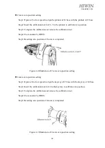
J5 -axis zero position setting
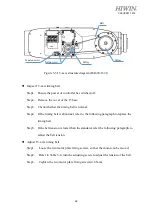
Step1: Operate J5 at low speed to align the pinhole of J6 base with the pinhole of J5 base.
Step2: Insert the calibration tool for J5 to the pinhole to calibrate zero position.
Step3: Complete the calibration and remove the calibration tool.
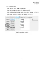
Step4: Clear encoder by HRSS.
Step5: Resetting zero position of J5 -axis is completed.
Figure 4-6Illustration of J5-axis zero position setting
J6-axis zero position setting
Step1: Operate J6 at low speed to align the keyway of EE with the keyway of J6 base.
Step2: Insert the calibration tool for J6 to the keyway to calibrate zero position.
(Previous version refer to Figure 4-7(b), align the calibration mark with the keyway.)
Step3: Complete the calibration and remove the calibration tool.
Step4: Clear encoder by HRSS.
Step5: Resetting zero position of J6-axis is completed.
4-7(a) 4-7(b)
Figure 4-7 Illustration of J6 -axis zero position setting
Mark for calibration
Calibration tool
Содержание RA620-1621
Страница 1: ...www hiwin tw User Manual Articulated Robot RA620 Original Instruction...
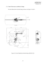
Страница 35: ...34 C08UE001 1912 Figure 2 3 Outer dimension and motion range RA620 1621 J1 0 deg...
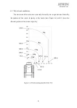
Страница 37: ...36 C08UE001 1912 Figure 2 5 Wrist load diagram RA620 1621...
Страница 54: ...53 C08UE001 1912 Table 5 3 Inspection schedule...

