


Chapter 4
Explanation of Functions
4-22
(3) Internal DC braking (A051: 01)
You can apply DC braking to the motor even without entering braking signals via the DB terminal when the inverter
starts and stops. To use the internal DC braking function, specify "01" for the DC braking enable (A051).
Use function "A057" to set the DC braking force for starting, and use function "A058" to specify the DC braking time for
starting, regardless of the braking mode selection (edge or level mode). (See examples 4-a and 4-b.)
Set the braking force for periods other than starting by using the DC braking force setting (A054).
Set the output frequency at which to start DC braking by using the DC braking frequency setting (A052).
When you set the DC braking wait time (A053), the inverter output will be shut off when the output frequency reaches
the setting of "A052" after the operation command (FW signal) is turned off, and the motor will run freely for the delay
time set by "A053". DC braking will be started after the delay (A053).
The internal DC braking operation to be performed when the operation command is switched from the stop command
to the start command varies depending on the braking mode (edge or level mode).
Edge mode: The DC braking time setting (A055) is given priority over operation commands, and the inverter
performs DC braking according to the setting of "A055". When the output frequency reaches the
setting of "A052" the inverter performs DC braking for the time set for "A055". Even if the stop
command is input during DC braking, DC braking continues until the time set for "A055" elapses. (See
examples 5-a and 6-a.)
Level mode: Operation commands are given priority over the DC braking time setting. The inverter follows
operation commands, regardless of the DC braking time setting (A055). If the start command is input
during DC braking, the inverter starts the normal motor operation, regardless of the DC braking time
setting (A055). (See examples 5-b and 6-b.)
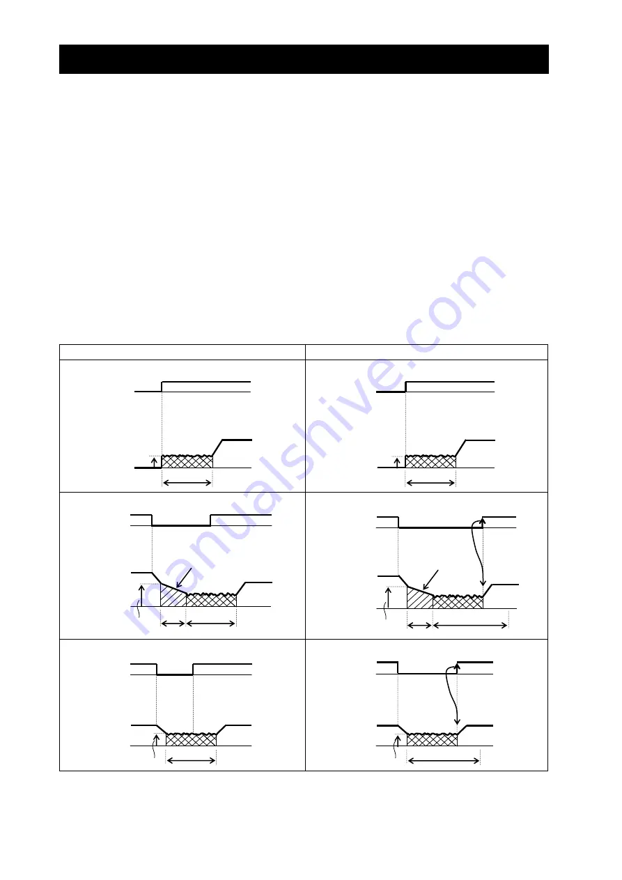
(a) Edge mode
(b) Level mode
i) (Example 4-a) when the start command is input:
i) (Example 4-b) when the start command is input:
ii) (Example 5-a) when the stop command is input:
ii) (Example 5-b) when the stop command is input:
ii) (Example 6-a) when the stop command is input:
ii) (Example 6-b) when the stop command is input:
A053
A055
A052
A053
A055
A052
A058
A057
A058
A057
A052
A055
A052
A055
Free running
Free running
FW
Output
frequency
FW
Output
frequency
FW
Output
frequency
FW
Output
frequency
FW
Output
frequency
FW
Output
frequency
Содержание SJ700-4000HFU2
Страница 16: ...Contents Appendix Appendix A 1 Index Index Index 1 ...
Страница 44: ...Chapter 2 Installation and Wiring 2 23 Memo ...
Страница 70: ...Chapter 3 Operation 3 25 Memo ...
Страница 246: ...Chapter 5 Error Codes 5 11 Memo ...
Страница 254: ...Chapter 6 Maintenance and Inspection 6 7 Memo ...
Страница 280: ...Chapter 8 List of Data Settings 8 17 Memo ...