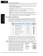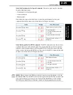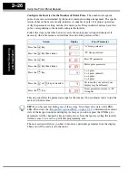
Using the Front Panel Keypad
In
v
e
rt
er Mounting
and Installation
2–24
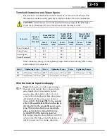
Selecting Functions and Editing Parameters
In order to run the motor for the powerup test, this section will show how to:
• select the inverter’s maximum output frequency to the motor
• select the keypad potentiometer as the source of motor speed command
• select the keypad as the source of the RUN command
• set the number of poles for the motor
• enable the RUN command
The following series of programming tables are designed for successive use. Each table
uses the previous table’s final state as the starting point. Therefore, start with the first and
continue programming until the last one. If you get lost or concerned that some of the
other parameters settings may be incorrect, refer to
“Restoring Factory Default Settings”
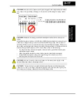
CAUTION:
If you operate a motor at a frequency higher than the inverter standard
default setting (50Hz/60Hz), be sure to check the motor and machine specifications with
the respective manufacturer. Only operate the motor at elevated frequencies after getting
their approval. Otherwise, there is the danger of equipment damage.
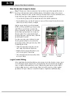
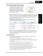
Setting the Motor Base Frequency
-The motor is designed to operate at a specific AC
frequency. Most commercial motors are designed for 50/60 Hz operation. First, check
the motor specifications. Then follow the steps in the table below to verify the setting or
correct for your motor. DO NOT set it for greater than 50/60 Hz unless the motor
manufacturer specifically approves operation at the higher frequency.
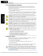
TIP:
If you need to scroll through a function or parameter list, press and hold the
or
key to auto-increment through the list.
Action
Display
Func./Parameter
Press the
key.
Monitor functions
Press the
or
keys until ->
“A” Group selected
Press the
key.
First “A” parameter
Press the
key twice.
Base frequency setting
Press the
key.
or
Default value for base frequency.
US = 60 Hz, Europe = 50 Hz.
Press the
or
key as needed.
Set to your motor specs (your
display may be different)
Press the
key.
Stores parameter, returns to “A”
Group list
FUNC.
d
0 1
1
2
A - -
FUNC.
A 0 1
1
A 0 3
FUNC.
6 0
5 0
1
2
6 0
STR
A 0 3
1
2
Содержание SJ100 Series
Страница 159: ...Inverter System Accessories In This Chapter page Introduction 2 Component Descriptions 3 Dynamic Braking 5 5 ...
Страница 186: ...Glossary and Bibliography In This Appendix page Glossary 2 Bibliography 8 A ...
Страница 194: ...Drive Parameter Settings Tables In This Appendix page Introduction 2 Parameter Settings for Keypad Entry 2 B ...
Страница 204: ...CE EMC Installation Guidelines In This Appendix page CE EMC Installation Guidelines 2 Hitachi EMC Recommendations 6 C ...
Страница 207: ...CE EMC Installation Guidelines Appendix C C 4 L1 L2 L3 PE M 3 SJ100 inverter with footprint type filter ...
Страница 208: ...SJ100 Inverter Appendix C C 5 L1 L2 L3 PE SJ100 inverter with book type filter M 3 ...

