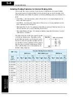
Configuring the Inverter for Multiple Motors
Oper
ations
and Monitor
ing
4–40
Configuring the Inverter for Multiple Motors
Simultaneous Connections
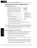
For some applications, you may need to connect two
or more motors (wired in parallel) to a single inverter’s
output. For example, this is common in conveyor
applications where two separate conveyors need to
have approximately the same speed. The use of two
motors may be less expensive than making the
mechanical link for one motor to drive multiple
conveyors.
Some of the characteristics of using multiple motors
with one drive are:
• Use only V/f (voltage-frequency) control; do not use
SLV (sensorless vector control).
• The inverter output must be rated to handle the sum
of the currents from the motors.
• You must use separate thermal protection switches
or devices to protect each motor. Locate the device
for each motor inside the motor housing or as close to it as possible.
• The wiring for the motors must be permanently connected in parallel (do not remove
one motor from the circuit during operation).
NOTE:
The motor speeds are identical only in theory. That is because slight differences
in their loads will cause one motor to slip a little more than another, even if the motors
are identical. Therefore, do not use this technique for multi-axis machinery that must
maintain a fixed position reference between its axes.
Inverter Configuration for Two Motor Types
Some equipment manufacturers may have a single type of machine that has to support
two different motor types—and only one motor will be connected at a time. For
example, an OEM may sell basically the same machine to the US market and the
European market. Some reasons why the OEM needs two motor profiles are:
• The inverter power input voltage is different for these markets.
• The required motor type is also different for each destination.
In other cases, the inverter needs two profiles because the machine characteristics vary
according to these situations:
• Sometimes the motor load is very light and can move fast. Other times the motor load
is heavy and must move slower. Using two profiles allows the motor speed, accelera-
tion and deceleration to be optimal for the load and avoid inverter trip (fault) events.
• Sometimes the slower version of the machine does not have special braking options,
but a higher performance version does have braking features.
to Nth motor
U/T1
V/T2
W/T3
Motor 1
Motor 2
SJ100
U/T1
V/T2
W/T3
Содержание SJ100 Series
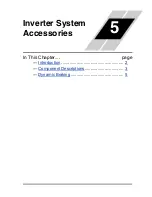
Страница 159: ...Inverter System Accessories In This Chapter page Introduction 2 Component Descriptions 3 Dynamic Braking 5 5 ...
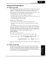
Страница 186: ...Glossary and Bibliography In This Appendix page Glossary 2 Bibliography 8 A ...
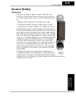
Страница 194: ...Drive Parameter Settings Tables In This Appendix page Introduction 2 Parameter Settings for Keypad Entry 2 B ...
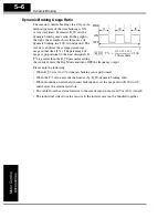
Страница 204: ...CE EMC Installation Guidelines In This Appendix page CE EMC Installation Guidelines 2 Hitachi EMC Recommendations 6 C ...
Страница 207: ...CE EMC Installation Guidelines Appendix C C 4 L1 L2 L3 PE M 3 SJ100 inverter with footprint type filter ...
Страница 208: ...SJ100 Inverter Appendix C C 5 L1 L2 L3 PE SJ100 inverter with book type filter M 3 ...

