PMML0175A-rev.1 - 6/2008
HARC-MODBUS - xxxxxxxxxxxxxxxxxx
4
HARC-MODBUS - Installation Manual
1. Safety Summary
2. Component names
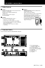
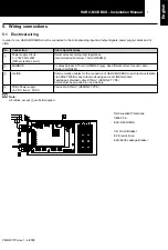
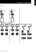
The figure shows the names of the HARC-MODBUS components.
Caution:
Do not connect voltage input to the control system before
installation is correctly done.
Read this manual carefully before performing
installation work.
Read this manual in order to configure
the HARC-MODBUS.
Attention:
Do not install HARC-MODBUS in places... :
– with vapour, oil or dispersed liquids.
– with heat sources nearby (sulphuric surroundings).
– where accumulation, generation or leaks of inflammable
gases has been detected.
– that are near the sea, in saline, acid or alkaline
surroundings.
Attention:
Install HARC-MODBUS away from possible sources
of electromagnetic waves.
Respect local electrical standards.
Use a power circuit that is not subject to peak demands.
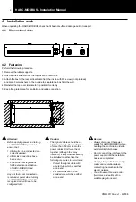
Ensure that there is enough free space around
the HARC-MODBUS (see figure) so that the heat may
dissipate adequately (refer to “Installation Work”).
If you install the HARC-MODBUS
in vertical position, install the power
supply in the lower part.
1
K1: H-LINK Connector:
Connected to CSNET WEB
2
K5: Serial port RS485
3
K3: +5V DC Power connection
4
Power source: 230V AC / 5V DC
5
H-LINK PCB
6
Packing glands (2)
7
7-segments
Содержание HARC-MODBUS
Страница 3: ......

