
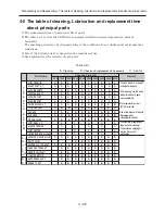


5 - 5
Adjustment > VCR Mechanism Adjustment
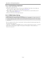
5-3-2 Tape Transport System Adjustment
When parts are replaced, perform the required adjustments, referring to the procedures for
adjusting the tape transport system. If there are any changes to the tape path, first run a T-120 (E-
120) tape and make sure that no excessive tape wrinkle occurs at the guide posts.
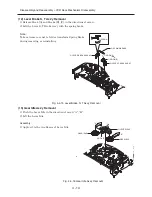
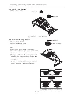
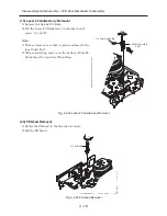
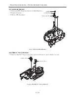
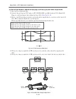
· If tape wrinkle is observed at the supply and take-up guide rollers, turn the supply and take-up
guide rollers until wrinkle disappears.
(See Fig. 5-3-1
and
Fig. 5-3-2)
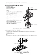
· If the tape wrinkle is still observed at the #8 guide post, perform the ACE head tilt adjustment.
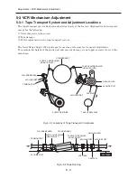
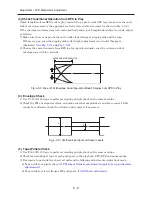
(1) ACE Head Assembly Adjustment
a. ACE Head Height Adjustment
1) Play back the alignment tape.
2) Observe the surface of audio head using a dental mirror.
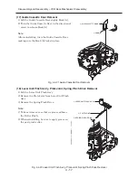
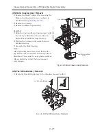
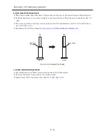
3) Turn screw (C) clockwise or counterclockwise until the gap between the lower tape edge and the
lower edge of control head is approx. 0.25 mm. (See Fig. 5-3-3 and Fig. 5-3-4)
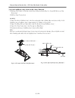
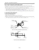
Fig. 5-3-3 Locations of ACE Head Adjustment Screws
Fig. 5-3-4 ACE Head Height Adjustment
SCREW (A)
TILT ADJUST
X-VALUE
ADJUSTING SLIT
SCREW (B)
AZIMUTH ADJUST
SCREW (C)
HEIGHT ADJUST
SCREW (D)
X-VALUE LOCKING
AUDIO HEAD
VIDEO TAPE
CONTROL HEAD
0 ~ 0.25 mm
Содержание DV-RF7U
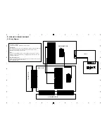
Страница 88: ...4 3 2 1 A B C D E F A B C D E F 8 7 6 5 4 3 2 1 8 7 6 5 C 2 CONDUCTOR SIDE ...
Страница 89: ...4 3 2 1 A B C D E F A B C D E F 8 7 6 5 4 3 2 1 8 7 6 5 C 3 C 2 Jack P C B COMPONENT SIDE ...
Страница 90: ...4 3 2 1 A B C D E F A B C D E F 8 7 6 5 4 3 2 1 8 7 6 5 C 4 CONDUCTOR SIDE ...
Страница 93: ...Copyright Hitachi Ltd 2004 All rights reserved I Digital Media Division Tokai TK No 0417E DV RF7U ...


