


4 - 4
Disassembly and Reassembly > Disassembly
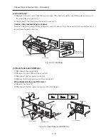
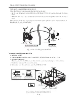
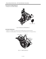
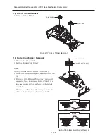
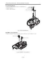
(6) Front P.C.B
1) Remove the FFC [portion a) in the figure].
When reconnecting the FFC, insert it into the connector, following the instructions in
illustration, and check the connection status.
2) Remove 2 screws [F] [portion b) in the figure], and then remove the Front P.C.B.
Fig. 4-2-5 DVD Main P.C.B, Jack P.C.B and Front P.C.B
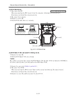
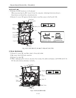
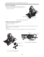
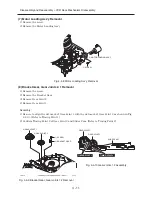
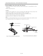
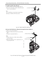
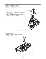
(7) Deck Mechanism
1) Remove 2 screws [D], and then remove the guide holder.
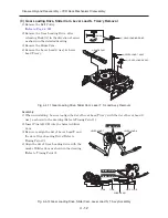
2) Disconnect the ACE head connector.
3) Remove 4 screws [E].
4) While unplugging the 3 direct connectors that connect the deck mechanism and VCR Main P.C.B,
lift the entire deck mechanism vertically.
Fig. 4-2-6 Deck Mechanism
4) FFC
a) FFC
5) Screw [F]
5) Screw [F]
b) Screw [F]
1) Screw [D]
1) Screw [D]
Direct
Connector
Front P.C.B
Jack P.C.B
DVD Main P.C.B
5) Screw [F]
[D] M3X12 (Gold)
[F] M3X8 (Gold)
3) Rear Panel
Parallel
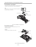
Insert the FFC so that it is
parallel to the connector.
After inserting the FFC,
check that the FFC doesn't
incline.
No Good
3) Screw [E]
3) Screw [E]
3) Screw [E]
1) Screw [D]
2) Connector
Direct
Connector
Direct
Connector
Guide Holder
[D] M3X12 (Gold)
[E] M4X12 (Gold)
Deck
Mechanism
Содержание DV-RF7U
Страница 88: ...4 3 2 1 A B C D E F A B C D E F 8 7 6 5 4 3 2 1 8 7 6 5 C 2 CONDUCTOR SIDE ...
Страница 89: ...4 3 2 1 A B C D E F A B C D E F 8 7 6 5 4 3 2 1 8 7 6 5 C 3 C 2 Jack P C B COMPONENT SIDE ...
Страница 90: ...4 3 2 1 A B C D E F A B C D E F 8 7 6 5 4 3 2 1 8 7 6 5 C 4 CONDUCTOR SIDE ...
Страница 93: ...Copyright Hitachi Ltd 2004 All rights reserved I Digital Media Division Tokai TK No 0417E DV RF7U ...


