


4 - 1
Disassembly and Reassembly
4-1 Order of Disassembly
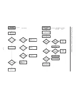
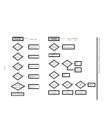
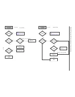
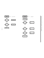
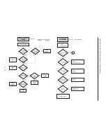
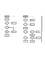
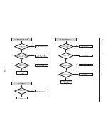
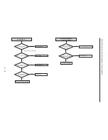
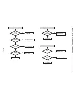
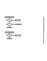
Refer to the Disassembly Flowchart in Fig. 4-1-1 for the order of removing components. When
reassembling components, use the reverse order to removal unless otherwise specified.
Reading Disassembly Flowchart:
After locating the target component in the flowchart, remove all components of the target in
sequence, following the arrows (routes) from the top of flowchart. If multiple routes exist to the
target component from the top of flowchart, remove all the components on all the routes.
4
Fig. 4-1-1 Disassembly Flowchart
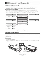
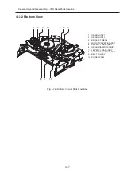
4-2 Cabinet Disassembly
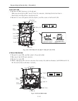
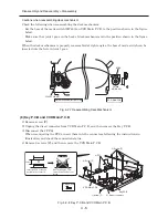
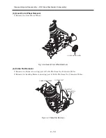
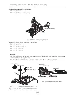
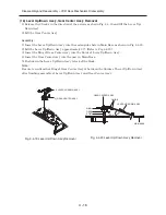
Information:
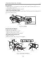
Numbers in figures are step numbers in disassembly procedure, and letters in brackets [ ] show the
types of screw.
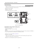
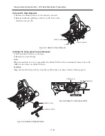
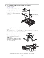
(1) Top Cover
1) Remove the 7 screws [A].
2) Slightly open both ends on the front side of top cover and lift the top cover in the direction of the
arrow.
Fig. 4-2-1 Top cover
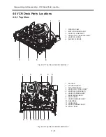
Key P.C.B
4-2 (8)
Front P.C.B
4-2 (6)
VCR Main P.C.B
4-2 (8)
Top cover
Parts to remove
Item
4-2 (1)
Rear panel
4-2 (3)
Front panel
4-2 (2)
FAN motor
4-2 (3)
Deck mechanism
4-2 (7)
DVD Multi drive
4-2 (4)
DVD Main P.C.B
4-2 (5)
Jack P.C.B
4-2 (5)
Parts to remove
Item
Parts to remove
Item
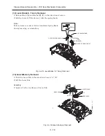
1) Screw [A]
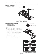
1) Screw [A]
1) Screw [A]
2)
2)
Top Cover
[A] M3X10(Silver)
Содержание DV-RF7U
Страница 88: ...4 3 2 1 A B C D E F A B C D E F 8 7 6 5 4 3 2 1 8 7 6 5 C 2 CONDUCTOR SIDE ...
Страница 89: ...4 3 2 1 A B C D E F A B C D E F 8 7 6 5 4 3 2 1 8 7 6 5 C 3 C 2 Jack P C B COMPONENT SIDE ...
Страница 90: ...4 3 2 1 A B C D E F A B C D E F 8 7 6 5 4 3 2 1 8 7 6 5 C 4 CONDUCTOR SIDE ...
Страница 93: ...Copyright Hitachi Ltd 2004 All rights reserved I Digital Media Division Tokai TK No 0417E DV RF7U ...


