


3 - 17
Details of Servicing and Troubleshooting > Troubleshooting
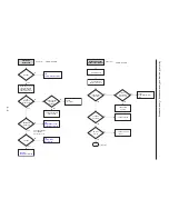
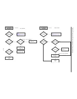
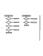
Is there
no 'P480' Mark on FLT?
CN3-12 on jack PCB
has
normal level?
Check the RCA cable
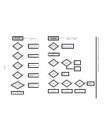
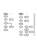
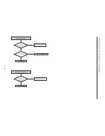
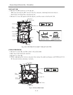
After DVDR is in stop state,
push the progressive scan key
on the Front panel.
No
No
Check Main PCB
Analog signals are
input normally
VIC1
No
No
No
Check the connection between
CN3-12 on Main PCB and VIC1
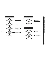
Power is
normal at VIC1-1,24, 34?
(Jack PCB)
VIC1-13 is
in high state?
Check the connection between
VIC1 and power
Check the connection between
VIC1-13 and VCR Micom.
Check VIC1 peripheral circuit
Yes
Yes
Yes
Yes
Yes
No
Video signal of
about 1V appears at
output jack?
Check the connection between
VIC1 and output jack
Yes
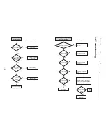
VIDEO output error
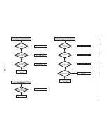
CN3-10, 8 on
jack PCB
has normal level?
Check the RCA cable
No
No
Check Main PCB.
Analog signals are
input normaly
VIC1 (Jack PCB)
No
No
No
Check the connection between
CN2-10, 8 on Main PCB and VIC1
Power is normal at VIC1-1,24, 34?
(5V)
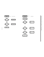
VIC1-13 is
in high state?
Check the connection between
VIC1 and power
Check the connection betweenVIC1-13
and VCR Micom.
Check VIC1 peripheral circuit
Yes
Yes
Yes
Yes
Yes
No
Video signals of
about 1V appears at
output jack?
Check the connection between
VIC1 and output jack.
Yes
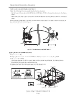
S-Video output error
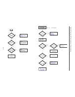
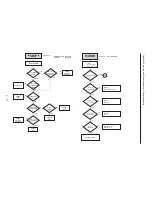
Is there
no 'P480' Mark on FLT?
After DVDR is in stop state,
push the progressive scan key
on the Front panel.
Содержание DV-RF7U
Страница 88: ...4 3 2 1 A B C D E F A B C D E F 8 7 6 5 4 3 2 1 8 7 6 5 C 2 CONDUCTOR SIDE ...
Страница 89: ...4 3 2 1 A B C D E F A B C D E F 8 7 6 5 4 3 2 1 8 7 6 5 C 3 C 2 Jack P C B COMPONENT SIDE ...
Страница 90: ...4 3 2 1 A B C D E F A B C D E F 8 7 6 5 4 3 2 1 8 7 6 5 C 4 CONDUCTOR SIDE ...
Страница 93: ...Copyright Hitachi Ltd 2004 All rights reserved I Digital Media Division Tokai TK No 0417E DV RF7U ...


