1-8-8
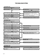
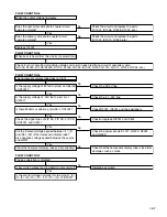
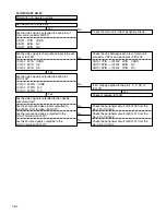
FLOW CHART NO.21
Picture do not operate normally.
Set the disc on the disc tray.
Are the analog audio interface signals outputted
to each pins of main unit connector CN701?
Are the system control interface signals outputted
to each pins of main unit connector CN701?
CN701 13PIN FL
CN701 15PIN FR
CN701 16PIN /AMUTE
CN701 14PIN /ZFR
CN701 12PIN /ZFL
Q1203 BASE /ZFL
Q1204 BASE /ZFR
Q1203, Q1204 BASE /AMUTE
IC1201 2PIN FL
IC1201 6PIN FR
Check the main unit. (IC601 periphery circuit.)
Check the main unit. (IC601 periphery circuit.)
Check or replace IC1201?
Check or replace Q1203 and Q1204?
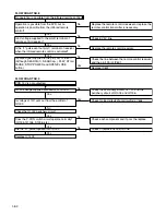
Check the peripheral circuit of AUDIO DAC
(IC801), AUDIO AMP. (IC1201) and audio mute
(Q1201, Q1202, Q1203 and Q1204) circuit.
Check the line between each pins of main unit
connector CN701 and each pins of IC1201.
Check the line between each pins of main unit
connector CN701 and each pins of Q1203 and
Q1204.
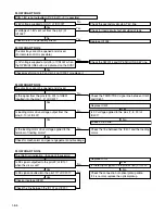
CN701 13PIN
→
IC1201 2PIN FL
CN701 15PIN
→
IC1201 6PIN FR
CN701 16PIN
→
Q1203, Q1204 BASE /AMUTE
CN701 14PIN
→
Q1204 BASE /ZFR
CN701 12PIN
→
Q1203 BASE /ZFL
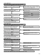
Are the analog audio interface signals inputted
to each pins of IC1201.
Are the system control interface signals inputted
to each pins of Q1203 and Q1204.
Are the audio signals outputted to the specific
output terminal?
Are the audio signals outputted to the L/R OUT
terminal (JK1201)?
Yes
Yes
Yes
Yes
Yes
Yes
No
No
No
No
No
Содержание DV-P725U
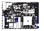
Страница 35: ...4 1 4 DVD Main 1 4 Schematic Diagram ...
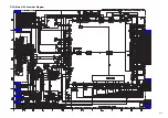
Страница 36: ...4 1 5 DVD Main 2 4 Schematic Diagram ...
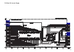
Страница 37: ...4 1 6 DVD Main 3 4 Schematic Diagram ...
Страница 38: ...4 1 7 DVD Main 4 4 Schematic Diagram ...
Страница 40: ...4 1 9 AV 2 3 Headphone Schematic Diagram ...
Страница 43: ...4 1 12 Progressive Schematic Diagram ...
Страница 44: ...4 1 13 Function CBA Top View Function CBA Bottom View Headphone CBA Top View Headphone CBA Bottom View ...
Страница 57: ...DV P725U DV P725U DV P725U No 9205E TK Digital Media Division Tokai ...

