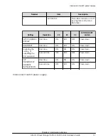

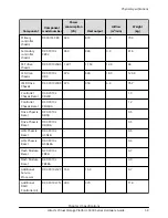
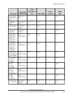


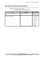


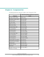

Item
Input
Power
Inrush Current
(Rating)
1
Leakage
Current
Inrush Current
When one
PS is
operating
When two
PSs are
operating
1st (0-p)
2nd (0-p)
1st (0-p)
Time
(-25%)
DBPS
(DBS2)
3.2 A
1.6 A
1.75 mA
30 A
30 A
25 ms
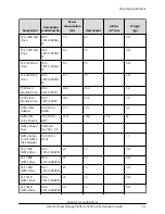
DBPS
(DBL)
2.0 A
1.0 A
1.75 mA
30 A
30 A
25 ms
DBPS
(DBF3)
3.1 A
1.55 A
1.75 mA
20 A
15 A
80 ms
DBPS
(DBN)
4.0 A
2.0 A
1.75 mA
30 A
30 A
25 ms
Node
interconn
ect switch
power
supply
1.2 A
0.6 A
1.75 mA
30 A
30 A
25 ms
1. When two power supplies are operating, each power supply provides about half of the
required power for the storage system. When only one of the two power supplies is
operating, the power supply provides all required power for the storage system. Therefore,
use the power supplies that meet the rated input current for when one power supply is
operating.
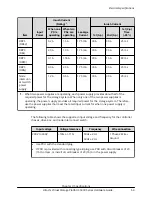
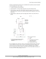
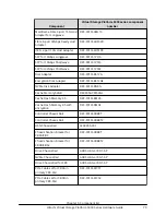
The following table shows the supported input voltage and frequency for the controller
chassis, drive box, and node interconnect switch.
Input voltage
Voltage tolerance
Frequency
Wire connection
200V to 240V
+10% or -11%
50Hz ± 2Hz
60Hz ± 2Hz
1 Phase 2 Wire +
Ground
■
Use PDU with the standard plug.
■
If PDU is provided with connecting type B plug, use PDU with circuit breaker of 20
(16) A or less, or install circuit breaker of 20 (16) A in the power supply.
Electrical specifications
Chapter 3: Specifications
Hitachi Virtual Storage Platform 5000 Series Hardware Guide
64


